I cant remember doping anything special.What did you change to lower the noise floor by ~15dB between post #1335 and #1337 - was it just the removal of the DUT from the loopback?
So it must be the DUT.
But I know that my load resistors (8ohm) did get really hot! When doping the stepped sina test.
Ryssen, looks to me like you have a ground loop or earthing issue. What does the soundcard look like noise wise with nothing connected to the mic / line input. Some soundcards do not work well with a basic loopback test.
The 'stepped sine' measurement within RTA has two options - you had the 'Step frequency' option selected within the 'Stepped Sine Measurement' settings pop-up box. I suggest you choose the 'Step level' option. That will then generate a plot to identify how HD % changes with level (at just one test frequency such as 1kHz), and when clipping occurs in your DUT.
Without any input I get a nice straight "curve".Ryssen, looks to me like you have a ground loop or earthing issue. What does the soundcard look like noise wise with nothing connected to the mic / line input. Some soundcards do not work well with a basic loopback test.
But when I insert the input jack the 50 and 150hz are back......And they wont go away even if I ground the input..
Last edited:
Yep seems to be a ground loop. Its a good thing to read up on. If its happening in your playback system you will improve the sound by fixing it.
Cant really figure out what its comming from.
Its just a cable.. It is a 1/4 plugg but it is made of plastic (well not the plugg but the cover)maybe thats the fault.?
Its just a cable.. It is a 1/4 plugg but it is made of plastic (well not the plugg but the cover)maybe thats the fault.?
I have just started using my Focusrite Solo to measure my amps. With loopback I have not been getting very good results. I have just read a post on this thread and I might be using the wrong input. I was using a TRS, should I be using the XLR?


Has the soundcard got a manual that identifies what you are connecting to/from?
Have you read the REW help on how to select input channel for a measurement?
Have you read the REW help on how to select input channel for a measurement?

Changed the driver and pressed the INST button and getting expected results. Thanks 🙏 It is now at 0.00039 THD after running the calibration on the preferences page I will now measure my QUAD405-1

To what? Something that can handle most devices, or just the Focusrite products?Changed the driver
When someone says "It looks like 16 bit Java asio drivers limitation", I dont understand; what else is there?
Looking to learn, here. Thanks!
There's a typo in the quote (asio shouldn't be in there), but the intent is correct. On Windows the JavaSound implementation, which is used when REW's "Java" drivers option is selected, is limited to stereo data at 16-bit resolution. I don't know how that came about, since JavaSound implementations on macOS and Linux are much more complete. Besides the 16-bit limitation Windows also uses a very short dither sequence for the data, which makes things even worse than 16-bit data should be. The solution is to switch to an ASIO driver, either the native ASIO driver for the interface or, if there aren't any native drivers or the input and output devices are different, an ASIO wrapper like FlexASIO.When someone says "It looks like 16 bit Java asio drivers limitation", I dont understand; what else is there?
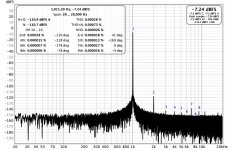
Hi all, I just want to share the results of a Motu M4 (close loop), a Motu M4 with a Akitika 1KHz sine wave generator and Analog Discovery 2
Motu M4 - Close loop, THD 0.00030% and THD+N 0.00092%
Motu M4 and Akitika - THD is 0.00028% and the THD+N is 0.00073%
Analog Discovery2 and Akitika - THD is 0.0161% and the THD+N is 0.02823%
Motu M4 - Close loop, THD 0.00030% and THD+N 0.00092%
Motu M4 and Akitika - THD is 0.00028% and the THD+N is 0.00073%
Analog Discovery2 and Akitika - THD is 0.0161% and the THD+N is 0.02823%
Attachments


Last edited:
The 'difficulty' with such plots is knowing how much harmonic distortion relates to the signal generator, compared to the signal ADC end. If the HDs are sufficiently above the noise floor, then it can be worthwhile adding in a - 20dB attenuator and checking if HD % stays the same. Another technique is to insert a notch. That type of testing may allow a better level of confidence, if the aim is to use your equipment for making measurements where distortions are down at the measurement equipment level.
I've been measuring tube amplifiers with REW. No such luck. There's more harmonics on a 1 kHz sine signal than REW can count...where distortions are down at the measurement equipment level.
the only time i tried to test a tube (valve for me 🙂) amp with this type of set-up it oscillated to a point i pulled the mains plug and never tried again!I've been measuring tube amplifiers with REW. No such luck. There's more harmonics on a 1 kHz sine signal than REW can count...
When measuring a tube (or valve) amp with a soundcard some test interface is usually needed to lower the voltages to levels suitable for the soundcard.
E.g. Pete Millett's test & measurement interface:
https://www.diyaudio.com/community/threads/test-measurement-interface-for-soundcard.155405/
Or Jan Didden's Autoranger:
https://www.diyaudio.com/community/threads/autoranger-for-soundcards.299635/
E.g. Pete Millett's test & measurement interface:
https://www.diyaudio.com/community/threads/test-measurement-interface-for-soundcard.155405/
Or Jan Didden's Autoranger:
https://www.diyaudio.com/community/threads/autoranger-for-soundcards.299635/
- Home
- Design & Build
- Software Tools
- How to - Distortion Measurements with REW