Certainly a weird and kinky idea. Two such different speakers blended together? Will be fascinating to see what comes of it.
However I can't really understand "why." Having heard Don Keeles' CBT and Tom Danley's SH50s in the same room less than an hour a part, I can say with confidence that as much as I like the CBT - the SH50 eats the CBT for luch. Really no comparison. Of course that isn't surprising given the size and power of the drivers used. But for tonal balance, imaging, scale, resolution, dynamics just about everything - the SH50 is clearly superior. But it's a whole lot more speaker, too. The size and efficiency differences make it hard to judge, so make of that what you will. If the CBT were much larger, could it equal the SH50? Maybe. I like the CBT but hands down I'd take the Synergy horn if I had to choose.
However I can't really understand "why." Having heard Don Keeles' CBT and Tom Danley's SH50s in the same room less than an hour a part, I can say with confidence that as much as I like the CBT - the SH50 eats the CBT for luch. Really no comparison. Of course that isn't surprising given the size and power of the drivers used. But for tonal balance, imaging, scale, resolution, dynamics just about everything - the SH50 is clearly superior. But it's a whole lot more speaker, too. The size and efficiency differences make it hard to judge, so make of that what you will. If the CBT were much larger, could it equal the SH50? Maybe. I like the CBT but hands down I'd take the Synergy horn if I had to choose.

Frequency shading is not really creating a spherical wavefront - or?
//
Your question is one of the reasons I keep coming back to the same projects over and over 🙂
Let me elaborate:

If you look at one of the Keele CBTs, you'll notice that the cabinet is significantly curved; the top of the cabinet is something like 40cm further back than the base. Part of this is to create a curved wavefront, no doubt. I have a theory that another thing that happens is that it becomes difficult to pinpoint where the sound is radiating from. I've heard both of the Keele CBTs and something that I noticed about them is that you can't really tell where the speaker location begins and ends. Right now in my office I have a pair of MTMs playing, and it's very easy to pinpoint the depth of the soundstage.
So I think this is one of those neat audio 'tricks', where when you close your eyes it's not 100% apparent if the speakers are six feet away or ten feet away. Danley SH-50s do this too.
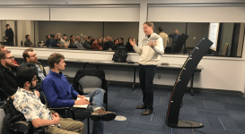
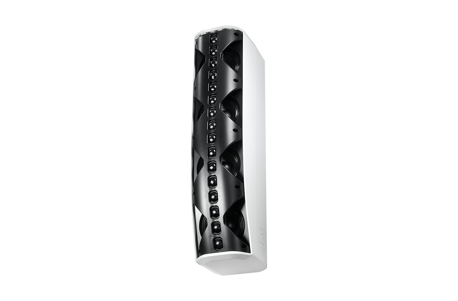
I think that the Danley SBH speaker sounds shockingly good, considering how compact it is and how it's using a bunch of diffraction horns for the tweeters. But having said that, the Danley SBH speakers don't do that trick; in the video that I recorded above, you can see that the sound gets noticeably louder as you get closer to the speaker. One of the strange things about the CBTs and the Danley SH-50 is that they DON'T do that; when you get closer, the speaker doesn't get noticeably louder.
I've told this one a hundred times, but our teenage daughter was sitting three feet away from a Danley SH-50 that I had in my living room, and she honestly asked "which speaker is on?"
IE, even though she was seated just three feet away(!) she couldn't tell if it was playing or not.

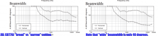
I've heard the JBL CBTs - which are noticeably narrower than the Keele CBTs - and they really don't sound much different than a conventional array to me. It was hardly a hifi environment - it was the lobby of the Virgin hotel in Las Vegas - but they didn't sound like anything special to me.
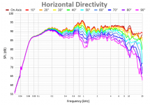

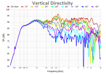
Finding high quality measurements of the CBTs is tough. Amir at AudioScienceReview measured the CBT70J on his Klippel, measurements are shown above. You can see that the vertical polars are kind of a mess TBH. For instance the response varies by about +/- 6dB, and even with an array of sixteen tweeters, the response is down six dB at 20khz.
This post isn't intended to savage the CBT design, in fact my main curiosity is why they sound good when they don't measure particularly well! I'm also kinda irked that the published documentation is clearly candy-coated and hyperbolic. I'd rather see published data, warts and all, and then let the engineers figure out why they sound as good as they do.
In the case of the CBT, here's my current hunch:
I've been studying the problem of "what makes a speaker sound good" for way too long, and the longer I study the problem, the more I think that dynamics and wide beamwidth is really important. I've been designing and building horns for almost 30 years now, and I think that one of the things that's really compelling about horns (at first) is that they're crazy dynamic. I'll never forget that day that I heard Harry Kimura's Acura Legend with it's horns, and the dynamics just FLOORED me. Unity horns get close to that ideal, and obviously I'm a big fan. But one of their drawbacks is that the mouth size just gets ridiculous if you want wide beamwidth. For instance, if you wanted to make a Unity horn with 135 degrees of horizontal beamwidth and 90 degrees of vertical beamwidth, and you wanted to control the vertical directivity down to 500Hz, you're looking at a horn mouth that's about FOUR feet wide! Not exactly something you can stick in your living room. There are some tricks we can do with enclosure shapes, and the more I study this problem, the more I think that the solution to the problem likely lies in exploiting that. Basically we can use the height, width and depth of the enclosure to control beamwidth to a much lower frequency than the baffle size would suggest.
Waaaaay back in the day, somewhere around 1992, I heard a demo of NHT's flagship speakers at SpeakerCraft in Riverside California. The NHTs imaged like nobody's business. I don't think anyone has put them on a Klippel, and I'm pretty sure that Ken Kantor was using a very very deep enclosure simply as a way to accomodate a 20Hz sub without resorting to a big ugly box. But I think he may have intentionally or accidentally stumbled on a way to get wide horizontal beamwidth while also reducing the sound of the room by simply having this gigantic monolith of a cabinet that kept a lot of the midrange and lower midrange radiation from interacting with the room.
Attachments
-
 2022-05-09 14_25_10-CBT Line Array Pics.png217.8 KB · Views: 110
 -
 2022-05-09 14_24_36-CBT Line Array Pics.png991.7 KB · Views: 103
 -
 2022-05-09 14_46_11-77037_JBL_CBT70J (Page 1).png122.5 KB · Views: 100
 -
 Horizontal Directivity 19.png24.1 KB · Views: 112
 -
 Vertical Directivity 20.png32.9 KB · Views: 116
I've been thinking this too lately and it is true, we see pattern control with varying box depth for example. Got into conclusion the effect is not bigger than what baffle can make, it seems to be less. All this can be very complicated, but I think it can be simplified for design purposes, here is the simplified reasoning:There are some tricks we can do with enclosure shapes, and the more I study this problem, the more I think that the solution to the problem likely lies in exploiting that. Basically we can use the height, width and depth of the enclosure to control beamwidth to a much lower frequency than the baffle size would suggest.
Baffle supports shorter wavelength than its size making about 6db boost, reflecting half of the propagating wave (bubble) to project outward from the baffle summing with the other half that already propagates away from the baffle, good ol baffle step. When wavelength is long, "the bubble" doesn't fit on it and it propagates to all directions. In addition, either the wavelength is long enough so that the baffle has no effect on it and it just goes around the edge propagating to back of the enclosure, or the wavelength is sufficiently short it diffracts at baffle edge, which creates opposite phase source which also propagates to all directions. It interferes destructively with the original wavefront to side and back so the sound that goes around corner is now attenuated. There is also a "back wave", part of the secondary source at the edge that propagates backwards, towards opposite side (and towards listener of course, any direction) which either makes constructive or destructive interference depending on wavelength and where one measures at. Here is illustration, "back wave" and attenuated sound around the corner visible. Main thing to notice is that both of these are attenuated in comparison to the direct sound propagating forward.

There are few things that affect the polar pattern, from all this:
- depending on wavelength the edge diffraction generated secondary source can boost the on-axis when it is in phase with it, and attenuate off-axis when out of phase. This is distinct "diffraction hump" seen on on-axis measurements and appear as narrowing response. This happens at baffle size wavelength and makes the most serious narrowing of speaker output, besides the baffle size.
- Now if the box is deeper than the baffle width, then part of sound that didn't mind the baffle edge and just went around might diffract at the back edge of the box. Same thing happens at the back edge as with baffle edge, diffraction back wave boost some axis, cancel some axis, some narrowing of response to lower frequency the deeper the box. This is the main effect that makes the pattern control I think, diffraction of the edges, in addition to the flat panel size. Also the high frequencies diffract at the back edge, but these diffracted at the front already attenuating them and the contribution to pattern is lot less, mere ripple.
Frequency where all these happen depends on the physical size of the box and physical size of sound, the wavelength.
The catch is, that the sound is already attenuated the further it is from the driver, behind baffle corner, scattered, so that anything that happens after the first corner can never have as much effect on the acoustic output as the first corner, a baffle or waveguide, has on it. On the baffle we have sound coming essentially from singular point ( thinking simple with one driver ) but at the back edge the sound is not coming from the driver directly but from the baffle edge, and trough other edges (around the box) and these are line sources with various delays depending on how long distance there is from the driver to the edge. This all makes contribution of the back edge "smeared" and its effect more distributed and in general, less.
While there is a chance to affect the output some with the box back shape, mainly on low frequencies below baffle step, I think the simplified bottom line is that after the baffle edge the game is kind of lost, we cannot control the sound too much anymore as it is already quite chaotic. Best bet for designer to really make difference in the acoustic response of the system is to do it with the front in where the control is not lost yet, by structure immediately next to the source. Basically it is a waveguide we want to have. If extending waveguide idea to a speaker box just think folding a smooth waveguide open as much as you like up until the whole construct is a sphere. Just don't make abrupt corners, impedance changes, which will make the secondary sources and lose the control, at least not before you have achieved the goal. What we can do with the back of the box is make round corners there to reduce all the ripple, beautify the graphs.
The main take away is the wavelength though, one really needs the size to have any control, it is not possible to have control to wavelength without comparable physical size, either the construct or source needs to be big to have control to low frequency.
Hopefully it wasn't too long a read 🙂
Last edited:
Isnt there a bit of contradiction between wanting a wide beam and the NHTs "kept a lot of the midrange and lower midrange radiation from interacting with the room"... I'm personally quite sure that a wide beamwidth is indeed the path to success for a natural reproduction of an orchestra. The narrow beaming speakers give to me a to great feeling of sitting in a loge/opera box. Its like a new acoustical environment is created on top of the real one. I dont like this at all. But I can see why people talk about pin-pointing etc - it is like a doll-house - everything is very neat and look real but it is ... small and not reality after all.
I listen a lot to a pair of floor-2-ceiling corner placed LAs. I used quite cheap Visaton FR 10 HM (10USD) 18 on each side. The top is problematic but at times these can sound absolutely fantastic. They do bass for sure - more than my country house can support really. I suppose they output a cylindrical sound field and I wish I could hear them with a spherical output. I need to find a really cheap D/A power amp (15W) solution to make the trial with a tot of say 32 channels...
In order to ease the size of the 500 Hz Unity you speak of, could not the corners be used to do this? I was a bit reluctant to use the corners as I have had the experience that it gives a dull sound... But now I'm convinced that it is really efficient once one can have full control of EQ.
//
This is very curious, from your description it seems hearing system cannot quite localize these speakers. Particularly interesting is that it doesn't seem to get louder closer up, I wonder what makes it so? Do you know any other speakers that give the same effect? Does the effect happen regardless of the environment where the speakers are at or is it just particularly good room and not the speaker alone that makes the effect?I think that the Danley SBH speaker sounds shockingly good, considering how compact it is and how it's using a bunch of diffraction horns for the tweeters. But having said that, the Danley SBH speakers don't do that trick; in the video that I recorded above, you can see that the sound gets noticeably louder as you get closer to the speaker. One of the strange things about the CBTs and the Danley SH-50 is that they DON'T do that; when you get closer, the speaker doesn't get noticeably louder.
I've told this one a hundred times, but our teenage daughter was sitting three feet away from a Danley SH-50 that I had in my living room, and she honestly asked "which speaker is on?"
IE, even though she was seated just three feet away(!) she couldn't tell if it was playing or not.
As all these examples are quite different in design and implementation in regards the physical construction, front and back of the enclosure, perhaps there is some aspects we could try to reason or at least speculate where the effect originates? While it could be from the construction, it doesn't seem to be diffraction for example, or perhaps it is? SH50 looks like it diffracts a lot (no roundovers) but perhaps some critical frequency band is diffraction free enough, as perhaps with the CBT as it seems much "smoother" while SBH is not as smooth in construction diffracting at some critical band to give up the location. All three have quite narrow vertical dispersion to quite a low frequency, while the arrays have wide horizontal dispersion SH50 has much narrower. All have kind of wild frequency responses, not too smooth. The other is point source while the other is not but they all have wide bandwidth response for the whole source height, not split up to lows and highs which would make different "images" through ceiling and floor for example, but MTM doesn't. Hmm, is it then in crossover implementation or something? Does the effect depend on SPL? Lots of fun figuring stuff out here!😀
Last edited:
I would suggest to try your idea in a simulation tool like Vituixcad first, as I don't see, after the several attempts I did, that the CBT is working as advertised in it's flyers.I listen a lot to a pair of floor-2-ceiling corner placed LAs. I used quite cheap Visaton FR 10 HM (10USD) 18 on each side. The top is problematic but at times these can sound absolutely fantastic. They do bass for sure - more than my country house can support really. I suppose they output a cylindrical sound field and I wish I could hear them with a spherical output. I need to find a really cheap D/A power amp (15W) solution to make the trial with a tot of say 32 channels...
In other words: I don't think we have seen much beyond some kind of ideal using very small sources. It would be rather difficult to repeat it with true life size drivers.
On top of that, the shading used throws away a lot of potential dynamics... I'd put my money on the Synergy.
Most of the high quality large horn systems I've owned and heard do this. It's uncanny. I could walk right up to my big Altec A5 with my chest almost touching the 1005 horns, but the sound still came from behind the speaker. Not vaguely, but very distinctly from behind. The sound never stuck to the speaker, it always seemed to be somewhere else. Patrick's description rings very true to me.Do you know any other speakers that give the same effect?
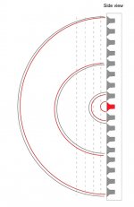
Yep, the CBT's curvature is pretty simple really....... 1/5th of wheel....72 degrees cut out of a circle......Your question is one of the reasons I keep coming back to the same projects over and over 🙂
Let me elaborate:
If you look at one of the Keele CBTs, you'll notice that the cabinet is significantly curved; the top of the cabinet is something like 40cm further back than the base.
I had to make a router circle jig with an 11ft radius to make a pair of these.. uses 24 TC9's.

My understanding of CBT's, is their intended use is setting of a floor in a room (unlike hanging line arrays).
The reflections formed by the arc acting with floor and ceiling, and the Legendre level shading, work together to make the curved line array magic.
Whether of not that implies a spherical wave front for some part of the freq spectrum, i dunno, but kinda doubt it. I think CBT is mainly about reducing floor and ceiling bounce comb filtering. just my laymen's take....
Anyway, i don't think a CBT is a good candidate for including a singular source of HF/VHF is its center. The curved geometry needs to be able to do its thing i think....I'd rather have a CBT with separate sized driver lines over its full length. Like tiny tweeter line, mid line, and bottom end line.
I'd rather use a straight line array if trying to use a central HF/VHF unit imbedded.
I played with the same 24 TC9's in a straight array, using freq shading to run only 3 or less TC9s in the center for HF/VHF, and using 1/4 c2c distances to progressively frequency shade in all the remaining driver. Sounded clearer, but of course with greatly reduced HF/VHF content.
I also tried timing delays and level shading (without frequency shading), first trying to mimic the CBT's outward curvature. Worked fairly well, but not quite the match for the CBT. Maybe if i had finer control, it would have been closer.....i only had 8 channels of amp and had to group drivers 3 at a time.
What was really fun with the straight array, was steering the center of the sound up and down the column. And either making the sound appear in front of the array or behind it, depending on concave vs convex delays.
For parties on the deck, this worked great...sound came from an apparent height of about 11ft. Nice even downward coverage that allowed easy conversation.

Anyway again, .... my 2c guess is a CBT will be a pain to work in a central HF/VHF source.
I suspect that with correct driver spacing it should be, but this is rarely implemented; Keele did it better than anyone else I have seen. Using 'full range' drivers - even little 3" ones - the HF is always going to be a complete mess of comb filtering!The fundamental issue with CBT arrays, and arrays in general, is that the high frequencies aren't well behaved.
I spent a lot of Vituix time trying to embed a tweeter, a waveguided tweeter, a synergized waveguided tweeter in a line array, with the central element properly blended in. None of them were any good. There is no way to match vertical directivity. Matching horizontal directivity is feasible but constrains driver width.
If you want to do this kind of thing, your best bet is the expanding array, perhaps with a small synergy at center. CBT is definitely not it. CBT has some arguably good points but it won't blend with a central element and indeed, the center of a ground plane CBT is a floor level where it meets its image.
If your reason for doing this is combing, it reduces with listening distance. LA is not for nearfield. At 4m or so, it shouldn't be an issue. Ironically, CBT is the worst choose re' combing. Wesayso and I were able reduce combing with shading but in CBT you don't have that option; Legendre shading is mandated. That is one of the reasons Don Keele went to such great lengths with his separate tiny tweeter line next to a line of small mids.that alone would have been sufficient for a conventional straight line array.
My understanding too. If c2c between highest freq drivers is 1/4WL or less, a line array holds without combing. So it really just comes down to the vertical spacing of the VHF/HF elements....how high in frequency can the line hold. In theory.I suspect that with correct driver spacing it should be, but this is rarely implemented; Keele did it better than anyone else I have seen. Using 'full range' drivers - even little 3" ones - the HF is always going to be a complete mess of comb filtering!
And is why the idea of a line array with multiple sized drivers running the entire line length has to sound better than a single sized driver array, i think.
all that said....
My 4 simplified line array takeaways:
a. Overall length determines lowest frequency of line control. Long is good!
b. Tightest c2c spacing of high frequency elements determines highest frequency before destructive interference. Tight is right!
c. no replacement for displacement, to get low end response. No replacement, no matter how many little drivers are at work.
d. high end doesn't work as well in theory as it should, no matter how tight c2c spacing...there's just something about a powerful point source that sounds less smeared
Iow, i'm with Pano...build a synergy/unity Lol
thanks for that.....makes total sense, and agrees with my experiments...I spent a lot of Vituix time trying to embed a tweeter, a waveguided tweeter, a synergized waveguided tweeter in a line array, with the central element properly blended in. None of them were any good. There is no way to match vertical directivity. Matching horizontal directivity is feasible but constrains driver width.
If you want to do this kind of thing, your best bet is the expanding array, perhaps with a small synergy at center. CBT is definitely not it. CBT has some arguably good points but it won't blend with a central element and indeed, the center of a ground plane CBT is a floor level where it meets its image.
If your reason for doing this is combing, it reduces with listening distance. LA is not for nearfield. At 4m or so, it shouldn't be an issue. Ironically, CBT is the worst choose re' combing. Wesayso and I were able reduce combing with shading but in CBT you don't have that option; Legendre shading is mandated. That is one of the reasons Don Keele went to such great lengths with his separate tiny tweeter line next to a line of small mids.that alone would have been sufficient for a conventional straight line array.
Based on my tinkering with various array projects, I've found that adding drivers on the horizontal axis can improve the frequency response and beamwidth on the vertical axis. I got some really good results with two-dimensional arrays here: https://www.diyaudio.com/community/...st-controlled-directivity-loudspeaker.347025/
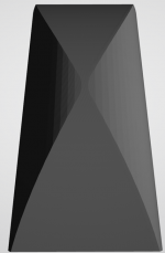
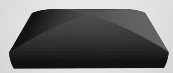
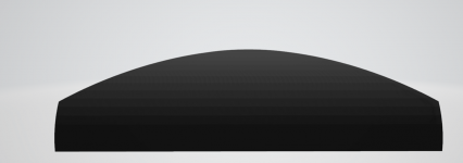
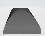
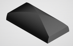
Last night I was tinkering with Keele's CBT, and I tried manipulating the baffle shape so that it's three dimensional. Basically the idea that the horizontal axis of the baffle would be a 180 degree hemispherical cap, and the vertical axis of the baffle would be a 60 degree vertical cap.
Based on CBT theory, that should lead to a horizontal beamwidth of about 136 degrees by 42 degrees. This assumes that the entire baffle is covered in radiators.
While tinkering with that, I began to notice it looked a heck of a lot like the speakers from Thiel and Hales in the 90s:


Stereophile isn't a particularly "technical" magazine, but in the 90s, a lot of their top rated speakers seemed to be "dipoles" and "speakers with crazy looking baffles." Methinks that the speaker designers of the 90s may have stumbled across solutions that improved directivity, but the reviewers weren't technically savvy enough to understand what was going on. Whenever I read those old reviews, I marvel at the fact that the authors will spend six paragraphs talking about the sonic properties of an RCA interconnect, but completely fail to comprehend that Nola speakers sounded different because they were dipoles.
Without building a replica of the Hales and Thiel speakers, I can't measure or comment on their beamwidth and frequency response. But based on what we know about baffles, I have a hunch that the curved baffle is controlling the beamwidth, similar to what a waveguide would do.
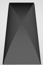
If we agree that wide horizontal beamwidth is GOOD and narrow vertical beamwidth is GOOD then we'd probably want a baffle that's a fraction of a hemisphere on the vertical axis, and a full hemisphere on the horizontal axis. If you took it to the extreme you might have the baffle curve around entirely in the horizontal axis.

If you did, it would look a lot like this.
I know I'm a broken record on this stuff, but the more I tinker with loudspeakers, the more I think that the marketing department convinces buyers that the secret sauce is in the drivers and the fancy wire, while the engineers who actually build these things understand that it's most about the cabinet. Hence, the top of the line speaker from Revel and Kef uses drivers that aren't much different than their cheap speakers. But their cheap speakers use monkey coffins and the expensive ones are shaped like a jellybean.
Last night I was tinkering with Keele's CBT, and I tried manipulating the baffle shape so that it's three dimensional. Basically the idea that the horizontal axis of the baffle would be a 180 degree hemispherical cap, and the vertical axis of the baffle would be a 60 degree vertical cap.
Based on CBT theory, that should lead to a horizontal beamwidth of about 136 degrees by 42 degrees. This assumes that the entire baffle is covered in radiators.
While tinkering with that, I began to notice it looked a heck of a lot like the speakers from Thiel and Hales in the 90s:
Stereophile isn't a particularly "technical" magazine, but in the 90s, a lot of their top rated speakers seemed to be "dipoles" and "speakers with crazy looking baffles." Methinks that the speaker designers of the 90s may have stumbled across solutions that improved directivity, but the reviewers weren't technically savvy enough to understand what was going on. Whenever I read those old reviews, I marvel at the fact that the authors will spend six paragraphs talking about the sonic properties of an RCA interconnect, but completely fail to comprehend that Nola speakers sounded different because they were dipoles.
Without building a replica of the Hales and Thiel speakers, I can't measure or comment on their beamwidth and frequency response. But based on what we know about baffles, I have a hunch that the curved baffle is controlling the beamwidth, similar to what a waveguide would do.
If we agree that wide horizontal beamwidth is GOOD and narrow vertical beamwidth is GOOD then we'd probably want a baffle that's a fraction of a hemisphere on the vertical axis, and a full hemisphere on the horizontal axis. If you took it to the extreme you might have the baffle curve around entirely in the horizontal axis.
If you did, it would look a lot like this.
I know I'm a broken record on this stuff, but the more I tinker with loudspeakers, the more I think that the marketing department convinces buyers that the secret sauce is in the drivers and the fancy wire, while the engineers who actually build these things understand that it's most about the cabinet. Hence, the top of the line speaker from Revel and Kef uses drivers that aren't much different than their cheap speakers. But their cheap speakers use monkey coffins and the expensive ones are shaped like a jellybean.
Attachments
-
 2022-05-10 12_09_54-may 9th cbt.stl - 3D Viewer.png103.1 KB · Views: 112
 -
 2022-05-10 12_10_29-may 9th cbt.stl - 3D Viewer.png43.2 KB · Views: 111
 -
 2022-05-10 12_08_32-may 9th cbt.stl - 3D Viewer.png67.7 KB · Views: 102
 -
 2022-05-10 12_08_13-may 9th cbt.stl - 3D Viewer.png44.4 KB · Views: 101
 -
 2022-05-10 12_07_53-may 9th cbt.stl - 3D Viewer.png28.7 KB · Views: 102
 -
 2022-05-10 12_07_13-may 9th cbt.stl - 3D Viewer.png334.2 KB · Views: 102
To me it looks like its all for reduce diffraction. Diffraction can make response to narrow around main diffraction hump but thats about it, perhaps extend bit lower with deep and elongated enclosure. Other than that it just creates problems to graphs, on-axis, power, DI, early reflections. For example the Blade, both vertical and horizontal plane for the mid/tweet is diffraction free, very smooth enclosure, no woofers on front causing diffraction! Woofers on the side and above and below the mid, not on the same plane, very good idea to take the woofers out from making diffraction for mid/tweet. Opposing woofers have added benefit, some vibration cancellation. I'm no KEF designer so its just speculation but all I see through my pink eyes is very low diffraction, very well optimized cabinet, probably the whole system is.
Same for the older speakers pictured, very good baffles for reduce diffraction, flatten power response etc, all good. If the corners weren't rounded, baffles less tall, there would be more distinct main diffraction hump and more ripple above. I bet these speakers measure quite well. I'm afraid there is no meaningful pattern control though, other than what comes with the baffle size, perhaps wee bit from depth. Although haven't seen what curved baffles do, perhaps there is some control available as well but no huge expectations, perhaps smoothing thins out a bit.
Same for the older speakers pictured, very good baffles for reduce diffraction, flatten power response etc, all good. If the corners weren't rounded, baffles less tall, there would be more distinct main diffraction hump and more ripple above. I bet these speakers measure quite well. I'm afraid there is no meaningful pattern control though, other than what comes with the baffle size, perhaps wee bit from depth. Although haven't seen what curved baffles do, perhaps there is some control available as well but no huge expectations, perhaps smoothing thins out a bit.
Last edited:
Illustrating what I tried to convey on the previous posts, how edge diffraction makes the narrowing response. It is clearly seen with ideal diffraction sims normalized polar responses and limiting to +-90 deg view so that the constructive interference on axis and slight destructive interference to sides really show up as narrowing response. First image has proper diffration hump visible slightly around 1kHz, it is only the front edge modeled (vcad diffcation tool) 34cm x 34cm and 8" flat piston on the middle to really maximise the diffraction hump. The other is the same, just with big roundovers (9cm radius) to take the hump out, response widens (to normal) where the hump is (just above bafflestep and somewhat into it) but otherwise directivity and other features stay pretty much the same.


To spice it up here are some full 3D enclosure sims by mabat https://www.diyaudio.com/community/...he-easy-way-ath4.338806/page-476#post-6972564 , on the next post the responses are in GIF animation for easier comparison.
Unfortunately the graphs are not same as here so it is not easy to compare, but to me it looks like the diffraction effect moves little bit lower as box depth is increased, otherwise the response (directivity) looks the same on all depths apart some ripple whose location varies some. Differences are very small, few db max although the graph seems to change dramatically, mind the scale. Similar effect as these two here, what diffraction makes.
I posted these to provide more info on your previous posts thoughts. It is just something I've observed happen with simulations and measurements. To me it all looks diffraction and effort trying to control it. Changes in directivity look like side product of diffraction to me 🙂 If liking wide response, reduce diffraction by rounding the construct to max, use roundovers where ever possible 😉
edit: here the same graphs, just scaled similarly to mabats graphs behind the link. Effect is similar, ~2db difference between the on-axis and 90 deg off-axis at diffraction hump. Diffraction makes response to narrow at wavelengths whose size is similar to baffle (or box).
Last edited:
Did that include delaying the line like a vertical arc with the central HF unit time aligned to its closest 2 neighbour LF drivers etc?I spent a lot of Vituix time trying to embed a tweeter, a waveguided tweeter, a synergized waveguided tweeter in a line array, with the central element properly blended in. None of them were any good. ...
//
Attachments
Wouldn' that put the tweeter on the floor if it is placed in a room? Otherwise the mirror image would be broken...
I posted these to provide more info on your previous posts thoughts. It is just something I've observed happen with simulations and measurements. To me it all looks diffraction and effort trying to control it. Changes in directivity look like side product of diffraction to me 🙂 If liking wide response, reduce diffraction by rounding the construct to max, use roundovers where ever possible 😉
I agree, and I think one of the challenges here, for me, is that I'm not professionally trained at this stuff. So I will sometimes use terminology that's inaccurate.
I think that Amir at AudioScienceReview and Erin at erinsaudiocorner have contributed a lot, and one of the most interesting contributions is seeing how enclosures impact frequency response and directivity.
Stereophile has published a lot of great information on speaker measurements, but their methods aren't particularly rigorous and their directivity measurements use a really bizarre format that went out of favor almost 30 years ago. I should buy Stereophile a Klippel lol.
I may be wrong, but the data that Erin and Amir have published, and the software that Mabat and you have published, seem to illustrate that it's possible to juggle these variables to extend directivity control an octave or two lower than you'd get with an infinite baffle:
1) enclosure height, width, depth
2) roundover diameter
If all of this is true, then it also means that there's another variable in loudspeaker design that we likely need to pay more attention to: the loudspeaker stand.

This table will significantly alter the polar response of the speaker.
Earl Geddes and I were chatting back in the day, and he noted that something as simply as having a potted plant near the speaker impacted how it sounded.
I think i understand what you hint at... wouldn't it rather be 1 floor down, mid up?Wouldn' that put the tweeter on the floor if it is placed in a room? Otherwise the mirror image would be broken...
//
- Home
- Loudspeakers
- Multi-Way
- CBT wrapped around a Unity Horn