Hello all. I'm new here. I don't know anything about circuit design. I'm an audio engineer and have soldered a bunch of cables (not that that really matters though).
I bought two Western Electric 111C transformers to run my mixes through. They sound good but I want to really push them. Problem is the SSL compressor clone I have before the 111C craps out at +22dbu. The 111C can handle +30dbm.
I've looked at hundreds of preamps online and only one has a max output past +28dbu and that's the Avalon Ad2022, but it's like $3k +. I'm thinking there has to be a way I can build a little box that can boost a +10dbu 600ohm signal to a max of around +35dbu 600ohm. Also the signal has to be balanced in and out, preferably XLR. I need two channels. A fixed gain boost would work but something with a gain pot would obviously give me more flexibility.
If anyone can help I'd appreciate it. I can do some soldering work if there's a kit, or I can pay someone to build it. Or it would be great if there's already little kit out there. Any help is greatly appreciated. Thanks.
Two power amplifiers driven in anti-phase, with or without series resistors? Is the purpose to get transformer distortion?
I'm not sure about your first comment. I'm not well versed in integrated circuits. The purpose is have the ability to reach the transformers point of distortion. Once I know what that level is and what it sounds like, I'll know when and how much level to send to it.Two power amplifiers driven in anti-phase, with or without series resistors? Is the purpose to get transformer distortion?
Just as a note I do have a -30dbu pad after the transformer so that it doesn't clip the analog to digital converter in my interface, which has a max input of +20dbu.
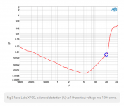
The Pass Labs XP-32 is a balanced-in, balanced-out, linestage preamp. It is capable of (a whole lot more than) +57dBu and its price is USD 17,500.
If you want to design and build your own gear, keep in mind that +37dBu into 600 ohms, is 18.5 volts peak-to-peak into 600 ohms. Which can easily be done by opamps whose datasheet specs guarantee both (a) output current > 20 mA , and also (b) power supply rail voltages >= ±15 volts. Possible choices include IC opamps and also professional-audio discrete opamps like the John Hardy 990.
All you need to do is design a balanced input receiver (perhaps using the THAT-1200 IC), a balanced output driver with gain set to your desired value (using two of the above opamps), and a phase inverter. Then lay out a PCB, select a chassis and ±15 volt power supply, (or ±24 volt power supply if using discrete opamps), wire up some XLR connectors and perhaps a volume control, done.
Thanks for the detailed response. Although I won't be able to design the circuit, I am not skilled enough. If I have the design and know what the parts are I could probably put it together myself.
I'll take a look at the THAT-1200 and see if that will work. Otherwise, I may have to go to Upwork or something and hire someone to do it. Or if anyone from this site is interested in making some money maybe we could work something out. I'm very hands on and would love to build it myself, I just don't want to get in over my head.
I'll take a look at the THAT-1200 and see if that will work. Otherwise, I may have to go to Upwork or something and hire someone to do it. Or if anyone from this site is interested in making some money maybe we could work something out. I'm very hands on and would love to build it myself, I just don't want to get in over my head.
I didn't know I had a group of circuit designers lol. And Nelson Pass sounds familiar... I think he designed the Adcom GFA-555 I had years ago when I had passive monitors. Very highly regarded amp. I think he did the mkii?Work with your group of circuit designers, I think you'll jointly conclude that this 25 year old Nelson Pass design probably meets & exceeds your requirements.
__
Anyway, thanks for the pdf. I still don't understand most of it but my friend gave me the number of his electrical engineer friend. I'm hoping he can help me take this project to the next step.
The Pass Labs XP-32 is a balanced-in, balanced-out, linestage preamp. It is capable of (a whole lot more than) +57dBu and its price is USD 17,500.
+57 dBu is 548.37 V RMS, or
1057/20 sqrt(0.6) V RMS to be precise.
Why on Earth would anyone design a preamplifier for such levels?
If you want to design and build your own gear, keep in mind that +37dBu into 600 ohms, is 18.5 volts peak-to-peak into 600 ohms. Which can easily be done by opamps whose datasheet specs guarantee both (a) output current > 20 mA , and also (b) power supply rail voltages >= ±15 volts.
+35 dBu is 43.56 V RMS, which for a sine wave is the same as 123.2 V peak-peak. As it is balanced, each side is 61.6 V peak-peak.
Possible choices include IC opamps and also professional-audio discrete opamps like the John Hardy 990.
All you need to do is design a balanced input receiver (perhaps using the THAT-1200 IC), a balanced output driver with gain set to your desired value (using two of the above opamps), and a phase inverter. Then lay out a PCB, select a chassis and ±15 volt power supply, (or ±24 volt power supply if using discrete opamps), wire up some XLR connectors and perhaps a volume control, done.
+/- 15 V or +/- 24 V is not enough to get 61.6 V peak-peak per side.

I thought +57 seemed a bit high.. I mean generally pro audio hovers around +20dbu as the ceiling, depending on your interface.
Thanks for chiming in with the voltage updates. I'm going to use as much of this info as possible to get this done, one way or another. One reason I want to do this so bad is that I estimate there aren't many people on this planet that have ever driven a 111C transformer as hard as it can go, given that most analog gear craps out at +22/+24 output. There are preamps that can do it, but I highly doubt many have gone through the effort to do it.
Thanks for chiming in with the voltage updates. I'm going to use as much of this info as possible to get this done, one way or another. One reason I want to do this so bad is that I estimate there aren't many people on this planet that have ever driven a 111C transformer as hard as it can go, given that most analog gear craps out at +22/+24 output. There are preamps that can do it, but I highly doubt many have gone through the effort to do it.
Also, the 111C manual says it is capable of +30dbm. What is the equivalent dbu of that for 600ohms (1:1)? I tried using calculators online but I don't understand the results because they are in dbuv.. I'm assuming dbu is a sound level measurement while dbuv is power/voltage. It's all so confusing. I really am just curious at what max dbu the 111C is rated..
dBuV (where the u should really be a mu) is dB with respect to a microvolt. It is often used for broadcast radio antenna inputs.
dBm is decibel with respect to 1 mW.
dBu is decibel with respect to the voltage that would produce 1 mW into 600 ohm, no matter what the actual impedance level may be.
So for 600 ohm, and only for 600 ohm, dBu and dBm are essentially the same.
dBm is decibel with respect to 1 mW.
dBu is decibel with respect to the voltage that would produce 1 mW into 600 ohm, no matter what the actual impedance level may be.
So for 600 ohm, and only for 600 ohm, dBu and dBm are essentially the same.
Is there a link to the Gerber files I have all the components be great to have the gerbers, Thanks for your time and help.Work with your group of circuit designers, I think you'll jointly conclude that this 25 year old Nelson Pass design probably meets & exceeds your requirements.
__
Are you also building a line amp?Is there a link to the Gerber files I have all the components be great to have the gerbers, Thanks for your time and help.
Oh ok so the unit is specd for +30dbu max output at 600ohms. I'd be interested if that holds up or if it can handle more... The literature ties that spec to 30hz-15khz, and I think it's the low end that starts to distort first (this tranny distorts non-linearly). That makes sense. I hope I can get this line amp built so I can do my own testing.dBuV (where the u should really be a mu) is dB with respect to a microvolt. It is often used for broadcast radio antenna inputs.
dBm is decibel with respect to 1 mW.
dBu is decibel with respect to the voltage that would produce 1 mW into 600 ohm, no matter what the actual impedance level may be.
So for 600 ohm, and only for 600 ohm, dBu and dBm are essentially the same.
Yes need a high headroom balanced line stage.Are you also building a line amp?
I've also looked into building a line driver capable of pushing a 111C into distortion. The published data says "Maximum level: +30dBm at 30 cycles", which probably means it's already into at least 1% distortion at that level. And when it comes to transformer saturation, the low end distorts first, it's a curve.
There is a direct relationship between the maximum output voltage of an amplifier and it's power supply voltage. An opamp typically uses a bipolar power supply, so a + and a - supply, usually +15 and -15 volts. Ignoring the fact that most opapmps cannot drive their outputs up to the fully supply voltage (rails), that means the maximum peak to peak output you can get out of a bipolar 15 V power supply amp is 30V p-p, which converts to +22.7dBu. If you make the output differential, using two amps out of phase, you get an additional 6dB for +28dBu. So clearly, 15V supply voltage is too low. If you had a couple of opamps that would run on bipolar 24V, you could do over +26dBu single ended, +32dBu differential. In real life, take off a dB or so because the opamp won't go to full supply voltage. In my case I have some 24 volt 990 opamps and an old board already socketed to mount them on, so that's what I'm doing to make my high output driver.
As a practical matter, most people looking into this are trying for "transformer color". The 111C is simply the wrong transformer to do that. It's "too good", and does very little at any reasonable level. People build these 111C color boxes and swear they round off the top end, mellow the middle, etc., blah blah blah. But they also went to a bit of effort to make the box, and all testing is fully sighted and biased. There's no telling if they really do anything audible. Measurements strongly suggest otherwise. But hey, if it makes them feel good, that's fine. But I'd also put a nice fresh coat of paint on those 111C coils to make them look and sound pretty.
Why not try something super simple and relatively cheap like using OPA552 instead of investing hundreds if not thousands of dollars just to see if you like the results.
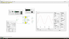
I'm sure the attached circuit isn't optimal since I barely know what I'm doing, but it looks like it should be able to do around +34dBu with a +10.5dBu input, which leaves room to adjust things with your compressor.
I'm sure the attached circuit isn't optimal since I barely know what I'm doing, but it looks like it should be able to do around +34dBu with a +10.5dBu input, which leaves room to adjust things with your compressor.
Attachments
- Home
- Source & Line
- Analog Line Level
- Line Amp Capable of +35dbu