what about a coaxial comp would that overcome the low end limitations of the comp? 3.5" ring diaphragm with +/-0.8 mm excursion for the BMS 4594
For me, too expensive. Would rather do bigger synergy with more low end extension and lower pattern control.what about a coaxial comp would that overcome the low end limitations of the comp? 3.5" ring diaphragm with +/-0.8 mm excursion for the BMS 4594
A pair of B&C 4NDF34 each with Sd 57.0 cm2 (8.84 in2) and Xmax of 3.4mm have far more output potential in the <1000Hz range for far less cost, and a 3" diaphragm HF driver has more HF output potential than the BMS 4594 or B&C DCX464 coaxial drivers.what about a coaxial comp would that overcome the low end limitations of the comp? 3.5" ring diaphragm with +/-0.8 mm excursion for the BMS 4594
Never mind the cost savings! A good quality 3" VC CD just isn't that expensive. A DCX464 ISA pair of B&C 4NDF34 each with Sd 57.0 cm2 (8.84 in2) and Xmax of 3.4mm have far more output potential in the <1000Hz range for far less cost, and a 3" diaphragm HF driver has more HF output potential than the BMS 4594 or B&C DCX464 coaxial drivers.
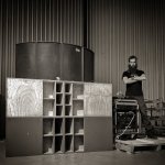
ab01ns, your SynTripP's look great !
Hey, to add a little to what Art's been saying about the 4NF34 against the BMS 4594, one of the experiments I've been running on my latest Syn10 build which has both these drivers in it, is the CEA 2010 wavelet bursts.
Thought the results might fit in well here....
This first set is a 1000 Hz burst at three different SPL levels. 85, 95, and 105 dB. These are LZmax values as per the REW meter, with meter on Fast.
(Ignore the main readout value, it was the room after the test burst.)
The LZpeak values are accurate too, usually about +25 dB to the Fast max.
The 4NDF34 mids (4) are on the left in all the comparisons, the CD on the right.
in order, 85, 95, then 105 dB.


Here's a set at 750 Hz, same order.


And the last set at 500 Hz.
In the final comparison, the BMS 4594 could not handle 105 dB....i had to back it down to 102 dB.
Kinda surprised me, given the BMS raw response trace on the Syn horn. I've included its trace after the burst comparisons. It's the red one, green is the 4NDF34's, and blue the 10" lows. (Lot's of room to juggle what's doing what)
It's pretty clear to me, taking CDs as low as they look like they can go by just looking at small signal, is fraught with peril .


Hope this all made sense....

Hey, to add a little to what Art's been saying about the 4NF34 against the BMS 4594, one of the experiments I've been running on my latest Syn10 build which has both these drivers in it, is the CEA 2010 wavelet bursts.
Thought the results might fit in well here....
This first set is a 1000 Hz burst at three different SPL levels. 85, 95, and 105 dB. These are LZmax values as per the REW meter, with meter on Fast.
(Ignore the main readout value, it was the room after the test burst.)
The LZpeak values are accurate too, usually about +25 dB to the Fast max.
The 4NDF34 mids (4) are on the left in all the comparisons, the CD on the right.
in order, 85, 95, then 105 dB.
Here's a set at 750 Hz, same order.
And the last set at 500 Hz.
In the final comparison, the BMS 4594 could not handle 105 dB....i had to back it down to 102 dB.
Kinda surprised me, given the BMS raw response trace on the Syn horn. I've included its trace after the burst comparisons. It's the red one, green is the 4NDF34's, and blue the 10" lows. (Lot's of room to juggle what's doing what)
It's pretty clear to me, taking CDs as low as they look like they can go by just looking at small signal, is fraught with peril .
Hope this all made sense....

Mark,And the last set at 500 Hz.
In the final comparison, the BMS 4594 could not handle 105 dB....i had to back it down to 102 dB.
Kinda surprised me, given the BMS raw response trace on the Syn horn. I've included its trace after the burst comparisons. It's the red one, green is the 4NDF34's, and blue the 10" lows. (Lot's of room to juggle what's doing what)
It's pretty clear to me, taking CDs as low as they look like they can go by just looking at small signal, is fraught with peril .
View attachment 1044199
If I understand what your test was, the BMS 4594 could "not handle 105 dB" at 500Hz means it had reached 10% harmonic distortion (-20dB harmonic distortion level) at 102dB "Fast" (123dB Peak), a "Fail" on the CEA-2010 Burst test.
Appears the four 4NDF34 were at approximately -50dB second harmonic level, under 1% distortion at 105dB "Fast" (127dB Peak) at 500Hz.
For the 4NDF34 to reach a CEA-2010 "fail" level at 500 Hz could require as much as 30dB more level, probably more voltage than your amp could produce without clipping.
What CEA-2010 level can the 4NDF34 "pass" at 200 or 300 Hz?
Art
Sorry for not being clearer. What i meant by 'could not handle 105 dB', was a mild diaphragm clank that was very obvious sounding with a reduction in SPL.
Nothing to do with CEA distortion pass/fail.
I've been using the 6.5 cycle CEA wavelets just to see how their spectrum looks. I've also used 1 cyc bursts, but their measured spectrum is considerably broader (given their more rapid start/stop i guess), and are less telling than the longer bursts.
I've been thinking CEA2010 distortion test was really only meant for subs. Do you think it would apply equally higher up ?
Also sorry for all the graphs I posted that were snips, of snips put together....resulting in small print and fuzzy text on the SPL meters LZ max and peak.
Here are new 500Hz snips for the 4NDF34 and BMS 4594HE both made at 101dB LZmax / 123dB LZpeak.
The four 4NDF34's at 9.6V..

The BMS at 23.4V. Only 2 dB higher is no go,....clank

Since the BMS is showing stress at 500 Hz levels below what i imagined, i'm think these short bursts are a harder test than I realize, and/or, maybe there is less output available at 500 Hz than appears looking at the raw curve.
On the raw traces i posted, i guess there is about -2dB response 500Hz vs 1000Hz. Checked traces without smoothing and they had same difference of less.
So i ran a 1000Hz burst, at same SPL as 500Hz, and measured 15.0V.......which gives 3.9dB vs 500Hz @23.4V.....and smells reasonable i think.
(The voltmeter is a Fluke 189, that supposedly captures and hold peaks of 0.25ms duration or greater. Seems pretty consistent so i think the readings are OK.)
Here's the 101dB 1000 Hz BMS.

I'm kinda left thinking, CEA bursts with their super narrow spectrum, register lower on a SPL meter than I would imagine.
System drive levels are at 0dB for these tests, with minor adjustments to get the same SPL on tests.
The generator drive level is the attenuation. This would be some loud *** music !!!
Any insights appreciated...
Nothing to do with CEA distortion pass/fail.
I've been using the 6.5 cycle CEA wavelets just to see how their spectrum looks. I've also used 1 cyc bursts, but their measured spectrum is considerably broader (given their more rapid start/stop i guess), and are less telling than the longer bursts.
I've been thinking CEA2010 distortion test was really only meant for subs. Do you think it would apply equally higher up ?
Also sorry for all the graphs I posted that were snips, of snips put together....resulting in small print and fuzzy text on the SPL meters LZ max and peak.
Here are new 500Hz snips for the 4NDF34 and BMS 4594HE both made at 101dB LZmax / 123dB LZpeak.
The four 4NDF34's at 9.6V..
The BMS at 23.4V. Only 2 dB higher is no go,....clank
Since the BMS is showing stress at 500 Hz levels below what i imagined, i'm think these short bursts are a harder test than I realize, and/or, maybe there is less output available at 500 Hz than appears looking at the raw curve.
On the raw traces i posted, i guess there is about -2dB response 500Hz vs 1000Hz. Checked traces without smoothing and they had same difference of less.
So i ran a 1000Hz burst, at same SPL as 500Hz, and measured 15.0V.......which gives 3.9dB vs 500Hz @23.4V.....and smells reasonable i think.
(The voltmeter is a Fluke 189, that supposedly captures and hold peaks of 0.25ms duration or greater. Seems pretty consistent so i think the readings are OK.)
Here's the 101dB 1000 Hz BMS.
I'm kinda left thinking, CEA bursts with their super narrow spectrum, register lower on a SPL meter than I would imagine.
System drive levels are at 0dB for these tests, with minor adjustments to get the same SPL on tests.
The generator drive level is the attenuation. This would be some loud *** music !!!
Any insights appreciated...
An obvious "clank" is a lot worse than the 10% distortion visible.Sorry for not being clearer. What i meant by 'could not handle 105 dB', was a mild diaphragm clank that was very obvious sounding with a reduction in SPL.
Nothing to do with CEA distortion pass/fail.
IIRC, (don't have REW in front of me) 1 cycle bursts have a "square wave" start point.I've been using the 6.5 cycle CEA wavelets just to see how their spectrum looks. I've also used 1 cyc bursts, but their measured spectrum is considerably broader (given their more rapid start/stop i guess), and are less telling than the longer bursts.
Probably not without some changes.I've been thinking CEA2010 distortion test was really only meant for subs. Do you think it would apply equally higher up ?
The test is no harder, but the LZF (Fast) is a 125 ms time constant, near the entire duration of 6.5 cycles at 500Hz (check my math...)Since the BMS is showing stress at 500 Hz levels below what i imagined, i'm think these short bursts are a harder test than I realize, and/or, maybe there is less output available at 500 Hz than appears looking at the raw curve.
You would have certainly heard multiple "clanking" if you ran a continuous sine wave at the peak level, possibly ruining the diaphragm.
1000Hz is 1ms per cycle, 500Hz 2ms per cycle, so the Fluke 189 are 5 times faster than "Fast" (125ms) 😉On the raw traces i posted, i guess there is about -2dB response 500Hz vs 1000Hz. Checked traces without smoothing and they had same difference of less.
So i ran a 1000Hz burst, at same SPL as 500Hz, and measured 15.0V.......which gives 3.9dB vs 500Hz @23.4V.....and smells reasonable i think.
(The voltmeter is a Fluke 189, that supposedly captures and hold peaks of 0.25ms duration or greater. Seems pretty consistent so i think the readings are OK.)
Well, now you know the output limit of the BMS is 123dB at 500 Hz on your horn, a lot less than a pair of 10"..Any insights appreciated...
Thanks,
Art
Hi Art, For sure !An obvious "clank" is a lot worse than the 10% distortion visible.
Nope, they are true 1 cycle sine wave bursts.IIRC, (don't have REW in front of me) 1 cycle bursts have a "square wave" start point.
Here are microphone grabs of latest synergy using 1.5 cycle bursts at 150 Hz and 700 Hz....
Yep, continuous sine would have surely busted the CD. I really like how we can feather the way up with the very short bursts, to find max without real risk.The test is no harder, but the LZF (Fast) is a 125 ms time constant, near the entire duration of 6.5 cycles at 500Hz (check my math...)
You would have certainly heard multiple "clanking" if you ran a continuous sine wave at the peak level, possibly ruining the diaphragm.
I don't really understand what "SPL filtered with a 125ms time constant means" (from REW SPL meter help) ...
i'm guessing it means RMS integrated over an 125 ms span..
At 2ms per cycle at 500Hz, i figure 6.5 cycles would be only 13ms...much shorter than the 125ms Fast time constant.
I'm also guessing that's why peak SPL of the burst is so much higher than SPL Fast. If SPL Fast had a time constant of say 12ms, maybe peak SPL vs Fast SPL would look more like a sine wave RMS vs peak......spitballing some here....
I dunno. The Fluke says it captures signal's maximums of 0.25ms or greater duration.1000Hz is 1ms per cycle, 500Hz 2ms per cycle, so the Fluke 189 are 5 times faster than "Fast" (125ms) 😉
I'm thinking that is analogous to a time constant (like SPL Fast), as it seems like that is the integrating time constant needed to produce a reading.
Which would make it 500x faster than SPL Fast...
Just to test even faster peak capture, i set up a scope to measure amp peak voltage, along with the Fluke, on single cycle bursts.
Sure enough, peak voltages read a bit higher on the scope than on the voltmeter, with the disparity increasing with frequency, as the voltmeters 0.25ms integration period becomes proportionally longer than the scopes.
With single cycle burst in the 4-5kHz range, where the period is close to the Fluke's 0.25ms capture spec, the scope read peaks about 1.4x the Fluke, like sine RMS to peak.
Maybe i'm just looking for 'understanding confirmation', but it appears like the Fluke effectively performs an RMS integration, when the single sine wave's period is close to its fast capture time.
I stay fascinated with peak vs average signal analysis....and sometimes get confused....Well, now you know the output limit of the BMS is 123dB at 500 Hz on your horn, a lot less than a pair of 10"..
Thanks,
Art
I think it has more to do with SQ than often given credit...
The truncated sine waves begin like a square wave. If those are screenshots of actual microphone grabs of a MEH output, that is remarkably better than I've seen.Hi Art, For sure !
Nope, they are true 1 cycle sine wave bursts.
Here are microphone grabs of latest synergy using 1.5 cycle bursts at 150 Hz and 700 Hz....
View attachment 1045210
That seems right, and similar to the way are hearing works-we can take handclaps and hammering nails at over 125dB peak without seeming too terribly loud, but a 1kHz sine wave at 100 dB does.I don't really understand what "SPL filtered with a 125ms time constant means" (from REW SPL meter help) ...
i'm guessing it means RMS integrated over an 125 ms span..
Yes. Seeing the difference between "peak" and "fast" levels can be surprisingAt 2ms per cycle at 500Hz, i figure 6.5 cycles would be only 13ms...much shorter than the 125ms Fast time constant.
I'm also guessing that's why peak SPL of the burst is so much higher than SPL Fast.
I think the difference in perception of peak vs average between individuals and the difference in dynamic headroom in loudspeakers may account for conflicting preferences that don't seem based on frequency response.I stay fascinated with peak vs average signal analysis....and sometimes get confused....I think it has more to do with SQ than often given credit...
Art
Exactly. The abrupt start and stop give a 'smallish square wave effect' and can be seen in the wider spectral content vs CEA's 6.5cycles bursts.The truncated sine waves begin like a square wave.
I'm guessing the reason CEA/Keele's burst are amplitude tapered at the beginning and end, are to reduce the start/stop spectral content.
Yes, true mic captures. Look like line level electrical, huh? 🙂 ......... The power of FIR, you know.If those are screenshots of actual microphone grabs of a MEH output, that is remarkably better than I've seen.
But they are kinda BS too, in that they were from a specific tuning to a close range spot. Never that good farther off, or tuned to a wider spatial average.
Would like some advice on speaker positioning / layout.
We built 4 SyntripPs a few years ago and had been using 2 of them for our mains and 2 without the horn extender as foldbacks, or sometimes fill speakers.
We now find ourselves usually wanting additional output for our mains. Curious if anyone has used these stacked vertically, with or without a splay (without the horn extender) and what worked best. Or even if it would be possible to have them stacked and build a larger horn extender that goes around both speakers.
Vertical stacking works OK, though with HF comb filtering in the area of overlap. With vertical splay, the combfiltering could be minimized, the lower HF driver attenuated, or run with separate DSP. Building a secondary horn that would allow variable splay would be tricky.We now find ourselves usually wanting additional output for our mains. Curious if anyone has used these stacked vertically, with or without a splay (without the horn extender) and what worked best. Or even if it would be possible to have them stacked and build a larger horn extender that goes around both speakers.
My advice would be to use mains cabinets that have the output desired, and use the SynTripP for fill speakers.
Art
Ultimately we may build some other mains, for now we have all of the SyntripPs on seperate Dsp channels so applying some attenuation to the lower HF is no problem. Any idea what a good starting angle would be for the splay? Time to get out the reference mic and start testing.Vertical stacking works OK, though with HF comb filtering in the area of overlap. With vertical splay, the combfiltering could be minimized, the lower HF driver attenuated, or run with separate DSP. Building a secondary horn that would allow variable splay would be tricky.
My advice would be to use mains cabinets that have the output desired, and use the SynTripP for fill speakers.
Art
The optimum angle would depend on the height of the array compared to the depth of coverage.Any idea what a good starting angle would be for the splay?
For a low ceiling, long room, no splay may be best, while around 15 degree splay for a shorter distance with a high mounting height could minimize front to back HF level difference.
Hi Art, I notice that in the first pictures you have your speakers/mic very high up do you have any tips on getting a microphone ~4m in the air so I can measure a larger (1.2m length) horn pointed at the sky in order to get polar plots of it? I was thinking a painters pole somehow attached to a weighted 35mm pole stand?
Tape or strap the mic boom stand to the speaker stand, with a second boom added would be ~4m.Hi Art, I notice that in the first pictures you have your speakers/mic very high up do you have any tips on getting a microphone ~4m in the air so I can measure a larger (1.2m length) horn pointed at the sky in order to get polar plots of it? I was thinking a painters pole somehow attached to a weighted 35mm pole stand?
To get a (semi) "free space" on axis measurement, a mic stand with two booms was strapped to the cabinet raised to 4 meters high:
The polars were measured at about two meters off the ground, with the mic centered on axis, the cabinet rotated on a turntable.
Deviations in frequency response due to ground reflections are evident in those measurements.
With your horn "pointed at the sky", ground bounce will be even more of a problem for both the cabinet and mic position, and won't be particularly representative of either free space or half space response.
Art
Hey guys!
Long time lurker, first time poster, I already sent this but it seems to have disappeared, do posts need admin approval for new users? either way if it reappears il delete one...
Big thanks to Art and the rest of the contributors to this great design. I am looking to upgrade my tops for outdoor parties up to around 500 people and this is one of my options.
I currently use Martin W3 (2 boxes per side splayed horizontally), they're running off a Powersoft M50Q with the recommended Martin corossovers/delay/EQ
While great sounding speakers unfortunately I dropped them recently and shifted the motors on 2 of the midbass drivers, I'm also not really happy with the top end "sparkle" they lack, especially on house and techno music.
This brings me to my questions, my current shortlist for replacements are 1 pair of SynTripP or 1 pair of 2x10 Paraflex, would either be able to provide similar (or greater) SPL and response than I'm used to?
The Paraflex' have the advantage of much easier build and array-ability over the SynTripP, but finding actual data on them seems to be tricky. Has anyone compared the 2 before? They are a similar size and use similar drivers but very different designs.
For the top end i'm considering these CDs as they're locally available for a reasonable price:
https://djcity.com.au/product/faital-pro-hf146r-1-4-inch-80w-109db-8-ohm-hf-driver/
Looking forward to your advice!
Attachments
Hi h3,
Welcome to the forum. 🙂 Yes indeed new members are moderated, and interestingly there were no other posts from you in the queue.
Welcome to the forum. 🙂 Yes indeed new members are moderated, and interestingly there were no other posts from you in the queue.
- Home
- Loudspeakers
- Multi-Way
- SynTripP: 2-way 2-part Virtual Single Point Source Horn