BC546/556 are not perfect. Agree. I switched to 2N3904/06 and they look slightly better in the switching region. But now I have to live with 40V devices in 45V powered circuit. Generally it's fine for the 1/2 supply location, but I'd prefer to be safer about that.I used BC546B and BC556B as splitters. The typical characteristics of these are not identical the former is more linear in its' 50uA working range outside of the turn on area. The BC556B plot has a degree of slope
One of the main points of the circuit according to Linsley-Hood was to avoid temperature issues with the output stage. The problem of setting bias currents for the output stage is then removed to the splitters. I used BC546B and BC556B in simulations. These give acceptable but not stellar results at 1kHz with low output quiescent current. Unfortunately things fall apart at 20kHz.
My 4 channels are ready and stable. I think I'll leave them as is for now and in the next few days will post my updated schematic. My goal was just to try the amp, but also to modify a little for 4-ohm load capability. Looks OK to me. The 2A set by Blomley is not enough to drive 4-ohm speakers when close to full voltage swing.
I think there are 2 places where thermals are involved. One is D4, D5 vs splitters, and the second is the D1, D2 vs. output stage. I find the splitters to be stable. Once set will stay pretty much the same. Output stage is not so stable and the idle current may rise some 40% at high power for long time. It definitely does some thermal tracking, but it's not enough. I don't think this is a problem though. For people wanting perfectly stable output idle current, the Onsemi devices with built-in diodes are probably the answer.
Simulation worked fine for me too. With exception of predicting all the parasitics that I have introduced with wires and PCB design. I did the Cf selection experimentally. I played with the splitter diodes as well and must say that they are not super critical. Actually the splitter will work OK even with one 1N4148, but my thinking is that jumping less gap during switching is better, so I added SD101A (replacing BAT46).
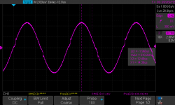
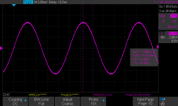
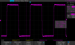
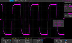
The 20kHz performance is not bad in the real amp. But if you try 100kHz, the trimmers would be to a much higher current than 38mA. I find that some 80mA make the 100kHz performance better. Interesting that setting the trimers depends also on the power level. Adjusting at, say, 15W requires more DC current to remove the crossover distortion than adjusting at 1W output power. Must be something related to dynamic parasitic effects... Interesting schematic, no doubt. I like dissecting its performance.
There are two main issues:
- the inputs cannot be left floating
- the start-up mess.
For future builders I attach 2 snapshots showing the crossover distortion at 100kHz/3Vrms/4ohm load. One is with no DC current and the second is with about 80mA.
I'm curious to read more about the re-designs that were proposed in this thread! No matter what, 4-ohm load is kind of a stretch for this circuit. I'm afraid it will become different amplifier if re-designed for that.
Attachments
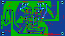
I have been looking at the beautiful printed circuit board that EGRA has develloped. It is a very compact design, but I saw some points of improvement. First of all I would like an option to choose differtent types of input capacitors, so provision is made for MKP capacitors with a 27,5 mm pitch. In the past, my Linsley-Hood Class A amp performed better with a high quality input capacitor. Furthermore the printed circuit track from the 33pF capacitor ( C5) should be as short as possible. So I changed the layout to accomodate a shorter track. Eventually the input of the amplifier and the output were quite close to each other, so the loudspeaker connectors now are located next to the power transistors. Finally I thickened the printerd cicuit tracks as much as possible and groundplanes are present on the top and bottom layer; these grondplanes need to be earthed by the user. If anyone has comments, please let me know
Attachments
- Hi Willem , I like your PCB/ Amplifier ideas!
- I have been interested in this amplifier having read some of the articles about it over the years. At one point I was even emailing back and forth with a fellow named Ken who had a website about the Blomley Amplifier called Thundernerd - he was going to build the amp and sell PCBs to others who were interested in the Amp... but after a while of sending emails back and forth he stop emailing me back -- I think he is okay because His website is still up, maybe he just got busy with life....
- So I was wondering if there was any posibility that you might have a few extra PCBs made up that I could buy from you?
- Thank you,
- Best regards, Dean

Hi Willem , Thank you for being willing to share , and well your probably right about making sure the pcb is correct first , , , 🙂
- After that the newbie in me would need to know how to go about using the the Gerber and Excellon files to place a pcb order - LOL .
- After that the newbie in me would need to know how to go about using the the Gerber and Excellon files to place a pcb order - LOL .
Hi Hallon83; I am a newby also, in relation to letting pcb's be made somewhere on the other end of the world. I used to make them myself with all kinds of chemicals. Regarding the pcb I have ordered a small batch (5 pcs) of a preliminary version. Then I was not satisfied and made other changes to the pcb. If this new version is OK, I will order for some more pcb's, but that will take several weeks as I am very busy at the moment.
2. Diode OA47 replaced by BAT46 low drop Schottky for obvious reasons of "unobtainium".
Thankfully I have a 2L (~ half gallon) plastic ice cream container full of stuff that I've saved since the 60's and I'm sure there will be the odd OA47 in there. However, you could also consider using a germanium transistor as a diode here.
More notes from my experience
Almost everyone in the development laboratory where I worked in 1971 built these (in those days we made printed-circuit designs with adhesive tape and circles on transparent film over hand-penciled designs!).
Letraset? Bloody luxury. I remember bitumen paint ...
Listening to quasi and full complimentary it is difficult to tell between the two (I very slightly prefer full comp but that could be for unrelated reasons). But the switch-off oscillation of quasi is horrible (and shows on the simulations). The thump of full comp is OK.And yet quasi-comp output amplifiers have received some accolades for their good sound (NAIM), including some highly popular Chipamps.
Member
Joined 2009
Paid Member
Many things can look awful on a 'scope, yet as you note, the ear is rather forgiving on this topic.
I have used Quasi Complementary amplifier designs and don't have any problem with these which included the Shaw/Baxandall diode modification to emulate the missing collector to base junction from the PNP driver transistor in the negative half of the amplifier. There were no switch off issues with these.Listening to quasi and full complimentary it is difficult to tell between the two (I very slightly prefer full comp but that could be for unrelated reasons). But the switch-off oscillation of quasi is horrible (and shows on the simulations). The thump of full comp is OK.
Julian Vereker of Naim Audio said of NPN and PNP power transistors that these are only really as equivalent as a man and a woman of the same weight and height. The problem as explained by Linsley-Hood is that "the different distribution of the N and P doped layers leads to significant differences in the HF performance of the devices. Thus, although the circuit may have good symmetry at low frequencies, it becomes progressively less symmetrical with increasing operating frequency. With modern transistor types, having higher transition frequency HF symmetry of fully complimentary output stages is improved, but it is still less good than desired, so the relative frequency/phase relationships of each half of the driver circuit may need to be adjusted to obtain optimum performance."
I have lived with a Naim amplifier for a long time. This has wife approval factor that any of my DIY amplifiers would never get. These are OK as long as they stay in the garage with all my other DIY projects.
Hi mjona,I have used Quasi Complementary amplifier designs and don't have any problem with these which included the Shaw/Baxandall diode modification to emulate the missing collector to base junction from the PNP driver transistor in the negative half of the amplifier. There were no switch off issues with these.
Julian Vereker of Naim Audio said of NPN and PNP power transistors that these are only really as equivalent as a man and a woman of the same weight and height. The problem as explained by Linsley-Hood is that "the different distribution of the N and P doped layers leads to significant differences in the HF performance of the devices. Thus, although the circuit may have good symmetry at low frequencies, it becomes progressively less symmetrical with increasing operating frequency. With modern transistor types, having higher transition frequency HF symmetry of fully complimentary output stages is improved, but it is still less good than desired, so the relative frequency/phase relationships of each half of the driver circuit may need to be adjusted to obtain optimum performance."
I have lived with a Naim amplifier for a long time. This has wife approval factor that any of my DIY amplifiers would never get. These are OK as long as they stay in the garage with all my other DIY projects.
I'm sure that the quasi-complimentary transistor configuration is fine with other amplifiers - it's just that, with the Blomley, it oscillates hideously on turn-off.
I think that the essence of Blomley's design is that the output stage is now unimportant, having split the signal BEFORE it gets to the output transistors at all. The only requirement of the output is that the gain is high enough (and a triple transistor ensures that) at the max current. Symmetry is not important because the transistor asymmetrical zone is bypassed by sufficient idle current into a linear zone (about 60mA seems to be quite good but open to trial). The asymmetrical gain is swamped by the resistor-controlled total gain of the output stage. The ratio of R20 / R17 and R21 / R18 set each output triple gain to 1000. If you reduce R17 and R18 for lower loudspeaker impedance you should probably reduce R21 and R20 to keep the triple gain to 1000 (this may be why just reducing R17 and R18 doesn't work well. (Over the past 45 years I have read Blomley's article many times and EVERY time I see something I read but didn't see it's importance. As I said in my original article, it's very dense information.)
If you get the Blomley amplifier right with an IC-free preamp, you are unlikely to ever want to listen any other amp. The pickup and the loudspeakers don't seem to matter much provided they are reasonably (not super) linear. The only device in the system that generates intermodulation distortion is the amplifier chain. If you do not get that rave effect, there is something wrong, period. You cannot use this amplifier for background music - your ear insists that the artists are looking at you funny because you are not paying them attention! Peter Blomley has designed a power amplifier that is very close to linear without any feedback (<1% harmonic distortion). (End of rave!)
Dermot
OA47 - I think is necessary because it is a gold-bonded germanium diode which has a lower forward voltage than most plain germanium diodes. They are available but prices range from €0.61 (https://www.fabian.com.mt/en/products/webshop/9298/germanium-diode-----10ma-25v-oa47.htm) to GB pounds 10 each (https://www.ebay.com/itm/261570991110)! The gold-bonded has quite different characteristics to the ordinary germanium diode.
If you get the Blomley amplifier right with an IC-free preamp, you are unlikely to ever want to listen any other amp. The pickup and the loudspeakers don't seem to matter much provided they are reasonably (not super) linear. The only device in the system that generates intermodulation distortion is the amplifier chain. If you do not get that rave effect, there is something wrong, period. You cannot use this amplifier for background music - your ear insists that the artists are looking at you funny because you are not paying them attention! Peter Blomley has designed a power amplifier that is very close to linear without any feedback (<1% harmonic distortion). (End of rave!)
Dermot
Hi Dermot,
thanks for the rave... I would be interested in running this amp fed by an USB interface which obviously is kind of an IC based pre-amp. Which measurable quantity would allow to judge, that the virtues of the Blomley amp are still being preserved, or would you exclude this right away?
OK, this is my final schematic. I consider this project finished. It’s time to put it in a box.
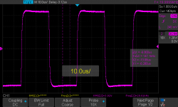
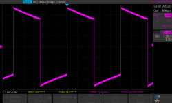
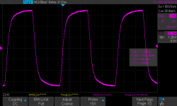
I uploaded the square wave response at several frequencies.
There are few small changes from the original, visible in the schematic. I made them mostly with the idea to drive better 4 ohm loads and to improve stability (which was not great with 1/2 closed loop gain than the original). The amp had a tendency to oscillate badly without load and/or without connected inputs. With the input RC circuit and the output Zobel I have pretty stable behaviour even with floating inputs and no load.
Another issue was hum. That required to split the input ground from the output/supply return. I did it as you’ll see in the schematic, which was the easy way for me. You can find better way to do it. Just be prepared that you’ll need it. Also some tests with different grounding arrangements will be necessary. This is not a quiet circuit!
Next issue was horrible start-up bang. Really scary and with expensive speakers not recommended. Actually, with any speakers is a bad, bad idea! I added slow start resistor/relay on the power supply... Slightly better, but issue was not solved. Unfortunately, this amp needs mandatory delay protection at the output to the speakers. Partially the issue is the DC bias of the input capacitor. Capacitors with DC bias are problem in audio and make the inputs extremely sensitive and ready to discharge where they are not supposed to. The RC circuit that I implemented tamed that at the expense of some input impedance drop.
Clipping behaviour is not very good. The circuit tends “to stick” into clipping. It doesn’t leave it unless the signal drops significantly. This is another good reason to protect your speakers or to play with the proposed circuit for soft clipping somewhere in this thread. I haven't try it, but it’s not bad to include it.
About the sound:
In the current version my Blomley is capable to output 25W into 4 ohm load. Frequency response is from few Hz to 300kHz (with Zobel and everything else included). Enough for me. Initially I wasn’t impressed by the sound at all. The amp sounded “hollow” and dead, compared to my other transistor Naim-like amp. It had a lot of noise (2MHz bandwidth can do that) and also bad hum.
I left it for a while and was ready to throw it in the trash, but then I added the mods described above and I think now the sound is really nice. Very different from the Naim sound, more close to a well designed tube amp. There is some fluid character. I like it a lot, but I need to listen more to be sure of what I hear. Would it make you think that real musicians are in the room – no, that ridiculous! But it will play in a very pleasant, understated way that encourages long listening. It’s not too bass-y, it’s not bright or dull. Just right... Matter of taste of course.
Good luck to anyone willing to build this old, but interesting circuit! It’s not for beginners, but is worth the effort and the money, I think.
Sorry for the long posts! I prefer it this way - put everything in one place, rather than writing 100 posts about the same.
Cheers,
Wes
Attachments
-
Blomley Schematic.pdf116 KB · Views: 354
-
 1kHz square - 2.png6.3 KB · Views: 260
 -
 20kHz square - 2.png7.8 KB · Views: 160
 -
 10kHz square - 2.png7.3 KB · Views: 161
 -
 50kHz square -2.png8.2 KB · Views: 138
 -
 100Hz square - 2.png6.5 KB · Views: 179
 -
 100kHz square -2.png8.9 KB · Views: 264
 -
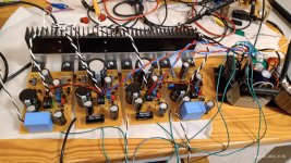 IMG_20220425_213554537.jpeg412 KB · Views: 255
Last edited:
Simulations are useful tools which can sometimes confound expectations or experiences of others who have built the particular circuit. Or vice versa. It is a strange world that we live in.
Measure a base -emitter junction of any germanium trz and you'll find a better diode than oa47 as a power trz offers also the opportunity of a good thermal contact by design! Just short the base to collector if you want higher current although you might just use only the be junction with a power trz. You can stick with the schotky diode though!OA47 - I think is necessary because it is a gold-bonded germanium diode which has a lower forward voltage than most plain germanium diodes. They are available but prices range from €0.61 (https://www.fabian.com.mt/en/products/webshop/9298/germanium-diode-----10ma-25v-oa47.htm) to GB pounds 10 each (https://www.ebay.com/itm/261570991110)! The gold-bonded has quite different characteristics to the ordinary germanium diode.
Attachments
Try simulating a Dolby C encoding decoding circuit if you want a glimpse of what reality means...In time I became a strong defender of " just enough quality that's never obvious"...everybody told us that DF over 100 are useless, yet you've never heard the true base on your recording until you've heard an amp with a DF that's well passed 500 at 50hz ...You use it with the least expensive woofers and you're baffled of how well controlled the base response is cause you never heard such a base even on very expensive speakers ... Yet it's so controlled that it sounds unnatural and suddenly you realize that not even the mastering engineer heard the true base on his recording because the usual active monitoring speakers aren't even close to that DF...Truth is that there's no real standard in audio because the audio material was mastered on specific equipment in a very controlled environement and you never have access to that while our pair of ears are much further from this technical game entirely.There's not a single amp that will ever be declared the absolute truth in audio as there's no common ground for all this objective and subjective experience.Simulations are useful tools which can sometimes confound expectations or experiences of others who have built the particular circuit. Or vice versa. It is a strange world that we live in.
I found (and I have) a lot more gold-bonded Ge diodes as AA117, AA143, OA95, 1N270, 1N276OA47 - I think is necessary because it is a gold-bonded germanium diode which has a lower forward voltage than most plain germanium diodes. They are available but prices range from €0.61 (https://www.fabian.com.mt/en/products/webshop/9298/germanium-diode-----10ma-25v-oa47.htm) to GB pounds 10 each (https://www.ebay.com/itm/261570991110)! The gold-bonded has quite different characteristics to the ordinary germanium diode.
http://njsemi.com/datasheets/OA99.pdf
Some people are sensitive to hearing phenomena than others. Once these are pointed out to others these can be detected. Sibilants were a case in point with me and I learned that about 30 years when a friend listened to a couple of amplifiers that I had built auditioned on his speakers at his home. He mimicked a sibilant sound by mouth and I have hated overemphasized sibilants whether due to amplifiers, loudspeakers or source material ever since. At the bass end of the audio spectrum this has to keep time with the music and drums should start with a bap rather than boom. This is probably more due to speaker design as amplifiers should have good damping factors if the power supply is engineered properly. I have built capacitor coupled output amplifiers and direct coupled ones. My preference is for direct coupling. The only capacitor coupled amplifier I built was the JLH 1969 Class A amplifier which is still popular - in my view the 1996 direct coupled output update is a better job.Try simulating a Dolby C encoding decoding circuit if you want a glimpse of what reality means...In time I became a strong defender of " just enough quality that's never obvious"...everybody told us that DF over 100 are useless, yet you've never heard the true base on your recording until you've heard an amp with a DF that's well passed 500 at 50hz ...You use it with the least expensive woofers and you're baffled of how well controlled the base response is cause you never heard such a base even on very expensive speakers ... Yet it's so controlled that it sounds unnatural and suddenly you realize that not even the mastering engineer heard the true base on his recording because the usual active monitoring speakers aren't even close to that DF...Truth is that there's no real standard in audio because the audio material was mastered on specific equipment in a very controlled environement and you never have access to that while our pair of ears are much further from this technical game entirely.There's not a single amp that will ever be declared the absolute truth in audio as there's no common ground for all this objective and subjective experience.
- Home
- Amplifiers
- Solid State
- The Blomley Class B amplifier