Chris,
What dc bias measurements are you running?
Is p2 1k?
Are you resetting the output to be 10v when putting the jumper in and out?
Is your meter good with 1kHz? What if you try at 100hz or 60hz?
What dc bias measurements are you running?
Is p2 1k?
Are you resetting the output to be 10v when putting the jumper in and out?
Is your meter good with 1kHz? What if you try at 100hz or 60hz?
Hi Chris,
Some comments: Your mosfets are quite well matched, so for future measurements it's adequate to just take one from the top and measure against one from the bottom. Just to confirm: You were unable to get the top and bottom values any closer together by any adjustment (clockwise or counterclockwise) of P2?
Any chance you used 500R for P2?
Edit: Just noticed Randy's reply. Also try a different (lower) frequency for testing.

Found the problem! Y'up, my P2 has a 500k pot. I had problems with out of stock, so I must have ordered the 500k twice, and didn't catch it.
Thanks so much guys for the help! You both were right on it, and correct!
I am just using a laptop with REW software for the test signal, so I thought it might be the problem, but it works fine, and so for those that don't have a signal generator, I recommend this option.
Thanks so much guys for the help! You both were right on it, and correct!
I am just using a laptop with REW software for the test signal, so I thought it might be the problem, but it works fine, and so for those that don't have a signal generator, I recommend this option.
Glad you found it!Found the problem! Y'up, my P2 has a 500k pot. I had problems with out of stock, so I must have ordered the 500k twice, and didn't catch it.
Thanks so much guys for the help! You both were right on it, and correct!
I am just using a laptop with REW software for the test signal, so I thought it might be the problem, but it works fine, and so for those that don't have a signal generator, I recommend this option.
If it's 500R (assume not 500k?)...
Do you have a higher value pot you could drop in?
If not, you could bump up the 392R resistor to something higher if you have a parts stash.
It's easier to replace a single resistor than a trimpot. Well, if you have a Hakko desoldering tool they're about the same effort.
If you go the route of replacing R21.
P2 @ 428R + R21 @ 392R = 820R
The idea was to have P2 roughly at the pot's midpoint so you have some room to adjust up and down. Now your midpoint is 250R with a 500R pot. So "ideal" is 570R + 250R pot = 820 with room to adjust up and down.
Something in the 500-650 range would be perfect. A little outside that range could also work. Hopefully, you have something in your box of parts and you're not making a $8 shipping charge on $0.25 in parts. You could always parallel some 1K's to get a 500R.
Let us know what you end up doing!
Another Aleph30 is born
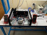
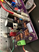
This has been by far my easiest and most pleasant build. Everything worked the first time, first the PSU (+20.7V, -20.7V loaded) then the amp itself. To make a short story shorter, while the start-up bias was 2.5A & 2.6A respectively, once the amp was warm I targeted 330mV across a typical source resistor on each channel and ended up with the following after an hour+ of playing music: Left channel, 335, 340, 336, 336, 337, 333mV; right channel, 339, 333, 328, 345, 333, 323mV. DC offset 27mV left channel, <7mV right channel. I only adjusted P3 to set Iq, I never touched P1 or P2, as I don't have the gear to set AC gain, and the DC offset was clearly fine on it's own. Super kudos to @rhthatcher's MOSFET matching skills.
Nota bene: this build uses a potentially novel combination of actives. Q1 and Q2 are matched pairs (again matched by rhthatcher) of the onsemi FQP3P20, while I kept the Q3 CCS as an IRFP9610. Instead of ZTX450s, I used onsemi 2N4401's.
I couldn't wait to play music, and didn't. This amp is both thrummy and deep and very resolved and detailed, like the noise floor, or at least a certain type of noise, dropped substantially relative to what I'm used to. Bass heavy tracks like Hold Me Tight by Johnny Nash are simply a joy. I've been listening to an ACA lately as I took my F3 down to use this chassis, and with some little 4" full range folded horns that are still breaking in, so it's hard to know just how detailed this thing is. But it was more than a match for my little Klipsch garage bookshelf testers, and I can't wait to put the chassis the rest of the way together and play it with my Seas A26, B1 buffer, Rega P3 and Emerald phono stage in my living room. I've been playing with the tweeter padding on the Seas lately to try and tone it down and I have a feeling this amp won't need it. Super fun!
Huge thanks to rhthatcher for designing these PCBs, matching all these MOSFETs, running the group buy, and of course to Papa for designing this thing and sharing it with us novices. Love this stuff.
Attachments
I used RN60D's which are 1/4W in my build. They are right at the tolerance point of fitting in this board, depending on how far the tan resin/glue extended on the leads. I had to squish some down but it worked fine, no standing soldiers or whatever.Is there enough room on the amplifier boards for Dale RN60 1/8W resistors? Standard Yaego/KOA are getting hard to hunt down but Mouser has all the sizes needed in the RN60 series but 8.7mm in length.
How about options for the 3W metal oxides? The recommended TE connectivity seems to a flame retardant metal film, not metal oxide. Are the Vishay wirewound 3W resistors an option? More expensive but at least in stock at Mouser for one stop shopping.
https://www.mouser.com/ProductDetail/Vishay-Dale/CW02B1R000JE12?qs=sGAEpiMZZMvNd0dY0KymzovlQjR29jmMNNIJTpLI78Q=
One last assembly question: any tricks to soldering Q1-3? With bigger Fets the legs and bent and attached to heatsink while soldering. Im obviously overlooking an easy way to stabilize Q1-3. And about Q1-2, I have IRF and Harris 9610s, as well as FQP3P20. My ignorant guess is the Harris 9610 has the potential to measure/perform better than its IRF counterpart. What about the FQP3P20? Different presentation like switching from stock IRF9610 to Toshiba 2SJ313?
ETA: What is the correct Neutrik XLR female jack to fit the 4U deluxe chassis cut out? Which of all the variations of the D series seems to fit/work the best?
https://www.neutrik.com/en/neutrik/products/xlr-connectors/xlr-chassis-connectors
Thanks
For 3W purposes I used the baby blue Panasonic ERX metal films throughout as I have a stash of them.
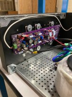
For Q1-3 I rolled up a little piece of masking tape, say 1/2cm tall, and stuck it on the legs on both sides of the transistor. This formed a little prop that I could then secure to the board or to other devices while soldering. This worked really well, the heights of Q2 and 3 came out quite similar and even.
Idk which Neutrik XLR fits, I used the Neutrik RCAs which fit the 4U deluxe cut-out. Mouser PN for the red one: 568-NF2D-B-2
Dan
Dan,
Thanks for the the sage advice. Got most of the parts here already, was able to find RN55s as Dennis suggested. Will definitely try the tape trick to get those transistors sitting up nice and high. Actually started working on PS parts last night. Hopefully I’ll have dueling Alephs, one Aleph 30 and one Aleph J (if the store ever gets boards back in).
Thanks for the the sage advice. Got most of the parts here already, was able to find RN55s as Dennis suggested. Will definitely try the tape trick to get those transistors sitting up nice and high. Actually started working on PS parts last night. Hopefully I’ll have dueling Alephs, one Aleph 30 and one Aleph J (if the store ever gets boards back in).
Dan,
Thanks for the the sage advice. Got most of the parts here already, was able to find RN55s as Dennis suggested. Will definitely try the tape trick to get those transistors sitting up nice and high. Actually started working on PS parts last night. Hopefully I’ll have dueling Alephs, one Aleph 30 and one Aleph J (if the store ever gets boards back in).
If you're up for some improvising, you could probably use the A30 boards for an AJ. I have some old aleph clone boards (Brian GT?) with the JFET legs twisted.
I not quite ready to join the Fearless Amplifier Builders club yet....
The store has board on order and due any day and I have all the parts for the store boards. I need to order 2 chassis anyway when they get the boards in. In the meantime I'll keep working slowing on the 2 power supplies so they will be ready to go. Already stuffed 8 snubber boards and 4 CL60 boards, going to work on the V8 mono PS boards tonight.
The store has board on order and due any day and I have all the parts for the store boards. I need to order 2 chassis anyway when they get the boards in. In the meantime I'll keep working slowing on the 2 power supplies so they will be ready to go. Already stuffed 8 snubber boards and 4 CL60 boards, going to work on the V8 mono PS boards tonight.
So I sat down tonight to build out the V8 CRCRC boards for both my Aleph J and Aleph 30. My plan was to use CDE 380LX 22k uF caps in all positions for the Aleph J boards and for the Aleph 30 was going to use the same 22k uf caps x2 for the first C but then 33k uF 380LX for the 2nd and 3rd C. Rational was typical DIY overkill with though that the Aleph 30 will eventually morph into an Aleph 60 so more capacitance is always better right? When I was ordering parts I was able to get all the 22k uF caps for a decent price, the 8 33k uF are still backordered. Also both Mouser and Digikey where short of enough of 5W ceramic resistors in 0.33 ohms, so I bought some 0.39 to use also.
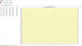
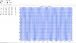
Before soldering everything in I figured I would play around with PSUD one more time out of the small chance using the 0.33 resistor vs 0.39 resistor would have any difference in combination with all 22k uF caps versus mixed 22k/33k uF caps. Now I will clearly admit that I am a PSUD super newbie but it looks like to me the different resistor values have minimal difference in ripple or output voltage. However, unless I am miss understanding the data it seems using all 22k uF caps has less ripple by a factor of almost 3 (looking at voltage at C3 and I1). Am I reading this correctly? If so, is the anticipated ripple low enough that this difference really doesn't matter? I don't have the 33k uF caps yet as they are backordered, Digikey has the 22k uF caps in stock now for almost 1/2 the price of the 33k uF version.
Before soldering everything in I figured I would play around with PSUD one more time out of the small chance using the 0.33 resistor vs 0.39 resistor would have any difference in combination with all 22k uF caps versus mixed 22k/33k uF caps. Now I will clearly admit that I am a PSUD super newbie but it looks like to me the different resistor values have minimal difference in ripple or output voltage. However, unless I am miss understanding the data it seems using all 22k uF caps has less ripple by a factor of almost 3 (looking at voltage at C3 and I1). Am I reading this correctly? If so, is the anticipated ripple low enough that this difference really doesn't matter? I don't have the 33k uF caps yet as they are backordered, Digikey has the 22k uF caps in stock now for almost 1/2 the price of the 33k uF version.
Attachments
I'm no expert, but those ripple results look way lower than they should. It appears you've set PSUD to use a constant current stepped load, which is giving you a load current of 100 mA - right from the off, possibly. That's resulting in much lower ripple than you ought to have, I suspect.So I sat down tonight to build out the V8 CRCRC boards for both my Aleph J and Aleph 30. My plan was to use CDE 380LX 22k uF caps in all positions for the Aleph J boards and for the Aleph 30 was going to use the same 22k uf caps x2 for the first C but then 33k uF 380LX for the 2nd and 3rd C. Rational was typical DIY overkill with though that the Aleph 30 will eventually morph into an Aleph 60 so more capacitance is always better right? When I was ordering parts I was able to get all the 22k uF caps for a decent price, the 8 33k uF are still backordered. Also both Mouser and Digikey where short of enough of 5W ceramic resistors in 0.33 ohms, so I bought some 0.39 to use also.
Before soldering everything in I figured I would play around with PSUD one more time out of the small chance using the 0.33 resistor vs 0.39 resistor would have any difference in combination with all 22k uF caps versus mixed 22k/33k uF caps. Now I will clearly admit that I am a PSUD super newbie but it looks like to me the different resistor values have minimal difference in ripple or output voltage. However, unless I am miss understanding the data it seems using all 22k uF caps has less ripple by a factor of almost 3 (looking at voltage at C3 and I1). Am I reading this correctly? If so, is the anticipated ripple low enough that this difference really doesn't matter? I don't have the 33k uF caps yet as they are backordered, Digikey has the 22k uF caps in stock now for almost 1/2 the price of the 33k uF version.
There's no way that bigger caps should lead to higher ripple, surely.
I agree, something is off on the simulation. I didn’t expect the ripple to go down with smaller caps and overall ripple seems to low. Probably is the load setup as you suggested, my understanding was these class A amps the current draw is relatively constant.
I agree, something is off on the simulation. I didn’t expect the ripple to go down with smaller caps and overall ripple seems to low. Probably is the load setup as you suggested, my understanding was these class A amps the current draw is relatively constant.
Your sims show that you have set a stepped load with an initial current draw of 2A, which then changes at some point in time to 100mA. I don't know when you have set the step to occur, but the ripple figures you're getting (1mV or less) imply a very low load, such as 100mA. To get a realistic sim, you need the load current to be something like 2.1A, surely.
Last edited:
So I sat down tonight to build out the V8 CRCRC boards for both my Aleph J and Aleph 30. My plan was to use CDE 380LX 22k uF caps in all positions for the Aleph J boards and for the Aleph 30 was going to use the same 22k uf caps x2 for the first C but then 33k uF 380LX for the 2nd and 3rd C. Rational was typical DIY overkill with though that the Aleph 30 will eventually morph into an Aleph 60 so more capacitance is always better right? When I was ordering parts I was able to get all the 22k uF caps for a decent price, the 8 33k uF are still backordered. Also both Mouser and Digikey where short of enough of 5W ceramic resistors in 0.33 ohms, so I bought some 0.39 to use also.
Before soldering everything in I figured I would play around with PSUD one more time out of the small chance using the 0.33 resistor vs 0.39 resistor would have any difference in combination with all 22k uF caps versus mixed 22k/33k uF caps. Now I will clearly admit that I am a PSUD super newbie but it looks like to me the different resistor values have minimal difference in ripple or output voltage. However, unless I am miss understanding the data it seems using all 22k uF caps has less ripple by a factor of almost 3 (looking at voltage at C3 and I1). Am I reading this correctly? If so, is the anticipated ripple low enough that this difference really doesn't matter? I don't have the 33k uF caps yet as they are backordered, Digikey has the 22k uF caps in stock now for almost 1/2 the price of the 33k uF version.
Regarding the choice of caps, in the first screenshot, with the lower ripple, the cap banks are 44mF, 33mF and 33mF. In the second screenshot, with the higher ripple, the cap banks are 44mF, 20mF and 20mF. Smaller caps, more ripple, as expected.
Play around in the simulator with the higher value cap in the position after the bridge. Then later in the chain. Let us know what you find.
Your sims show that you have set a stepped load with an initial current draw of 2A, which then changes at some point in time to 100mA. I don't know when you have set the step to occur, but the ripple figures you're getting (1mV or less) imply a very low load, such as 100mA. To get a realistic sim, you need the load current to be something like 2.1A, surely.
Regarding the choice of caps, in the first screenshot, with the lower ripple, the cap banks are 44mF, 33mF and 33mF. In the second screenshot, with the higher ripple, the cap banks are 44mF, 20mF and 20mF. Smaller caps, more ripple, as expected.
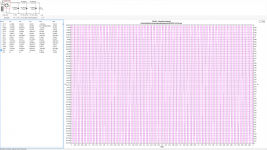
Will apologize for the thread drift and mini PUSD tutorial. Ok I went back in and changed current load to steady 2.1A draw, no step. Also realised I entered the cap values incorrectly 44mF, not 44uF. Have corrected that also and done some more simulations. I still think something is off. With the changed I am getting any error message "current sink has pulled voltage below zero for more than 5 mains cycles".
Also so I am clear, what I am interpreting as ripple is the delta of V P-P at V(C3) or V(I). So looking at the charts roughly 13.8mV which still seems too low for a CRCRC PS.
Play around in the simulator with the higher value cap in the position after the bridge. Then later in the chain. Let us know what you find.
Not convinced I have everything entered into PSUD correctly yet, as soon as I am I will report back. Seems like a Mark Johnson homework lesson.
44mF was correct. 44mF = 44,000uF.Will apologize for the thread drift and mini PUSD tutorial. Ok I went back in and changed current load to steady 2.1A draw, no step. Also realised I entered the cap values incorrectly 44mF, not 44uF. Have corrected that also and done some more simulations. I still think something is off. With the changed I am getting any error message "current sink has pulled voltage below zero for more than 5 mains cycles".
Also so I am clear, what I am interpreting as ripple is the delta of V P-P at V(C3) or V(I). So looking at the charts roughly 13.8mV which still seems too low for a CRCRC PS.
View attachment 1049788
Not convinced I have everything entered into PSUD correctly yet, as soon as I am I will report back. Seems like a Mark Johnson homework lesson.
PS No need to apologise - I'm probably about a week ahead of you with PSUD. 😎
PPS Your ripple voltage in that screenshot is the diff voltage at the load - 23.443volts!
Last edited:
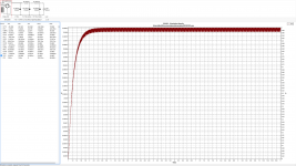
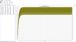
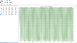
Allright, should be the last screenshots as I think I have everything in correctly. Ripple voltage still seems to be lower than I would expect, but also is output voltage at not quite 22V. Was expecting more like 24-25V. If the ripple numbers are close to correct, it doesn't seem to make much difference if the larger caps are in the first C after the bridge as opposed to the 2nd and 3rd C.
Attachments

Looks pretty good now. You could maybe tweak how the transformer is entered. (I've been entering the manufacturer's numbers for nominal voltage, secondary current and regulation in the "Off-Load Voltage Calculator" dialogue box. I think that should give a more realistic sim. I hope that's the right way to do it.)Allright, should be the last screenshots as I think I have everything in correctly. Ripple voltage still seems to be lower than I would expect, but also is output voltage at not quite 22V. Was expecting more like 24-25V. If the ripple numbers are close to correct, it doesn't seem to make much difference if the larger caps are in the first C after the bridge as opposed to the 2nd and 3rd C.
When I sim with the same numbers, I get a few extra mV of ripple, for some resson, but its close.
As for the lowish rail voltage, adjusting how the transformer is entered may push up your numbers a little. But, yes, an 18V transformer doesn't seem to get the rails as high as you'd think. There were posts earlier in thread about this, I think, and some suggestions about rectification, which might help. (See post #293 and responses.)
Last edited:
Great! Learning has occured today. I went back and added the exact transformer specs from Toroid Corp's build sheet, which included the resistances on the primary/secondaries and measures output on secondaries which are a little over spec at 19.3V RMS. Last set of screensheets look as good as I think I will get them. Thanks again for the help navigating PSUD, I believe at this point I am seeing real numbers.
Randy, does seem that the larger 32uF caps in the 2nd/3rd C shows the lowest estimated ripple, then 32uF capsX2 as first C and 22uF as 2nd/3rd C, then all 22uF caps.
Regarding the rectifiers, I had seen post 293 before ordering my parts. So I went ahead and got the Vishay VS-26MB-40A bridges Tungsten mentioned hoping for lower V loses. I also ordered Randy's handy snubber boards which I what I had soldered up the other night. What the rookie missed is that while the VS-26MB-40A may look like the GBPC package its not the same package, blade orientation is different on one side. So I know have both the VS-26MB-40A and the GBPC3502-E4/51 Randy listed in the BOM which play nicely with his snubber boards. So I should be able to test both bridges see I there is a significant difference in V drop.
Which brings me to my last learning opportunity of the day. I have seen multiple people mention testing there power supply builds in stages as they go ie: hook up mains to primary through CL60 boards and test, test again when secondaries are hooked up to bridges, test again when bridges are hooked up to PS filter boards, and finally test when hooked up to actually amplifier boards with real use loads. At the earlier stages of testing what type of load do you use while testing? Can you use something like a 8R speaker load resistor across the secondaries, then bride output, and finally PS filter output while measuring?
Attachments
- Home
- Amplifiers
- Pass Labs
- Classic Aleph Amplifier for Modern UMS Chassis Builder's Thread