I believe found the LXstudio multi-way at the store
https://linkwitz.store/product/asp-lxmini2-nelson-pass/
along with a guide thread
https://www.diyaudio.com/community/threads/balanced-3-way-asp-nelsonpass.335847/
Hope they’re the best places to start.
https://linkwitz.store/product/asp-lxmini2-nelson-pass/
along with a guide thread
https://www.diyaudio.com/community/threads/balanced-3-way-asp-nelsonpass.335847/
Hope they’re the best places to start.
Hello members,
I've got a request from member PC997. He wants to drive his two-way-speaker (with passive crossover)
actively. Why not try to build a 6-24 active crossover (6-24 AXO)?
The drivers are:
SEAS W16NX-001/8 (MidBass), frequency range around 45Hz - 2500Hz
SEAS T25CF-001 (dome-tweeter), frequency range around 2000Hz - 25000Hz.
He sent me informations about the passive crossover and some SPL-graphs. I checked on the SEAS-internet-
site to get some infos about the drivers. I know the tweeter, but never used the Midbass W16NX-001/8.
I will add some pics below.
I asked PC997 if we shouldn't discuss this here in the public. Why? Because I think there are a few members out
there, who are thinking about this. Whether experienced or 'beginner level'.
And I am also not Mr. I-know-everything... No, I am learning every day.
Cheers
Dirk 😉
Attachments
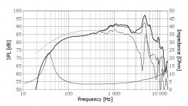
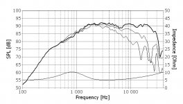

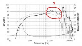
On the third pic you can see the summed SPL-curve with the passive crossover.
Crossover frequency is clearly at 2000 Hz.
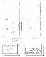
When I checked the schematic of the passive crossover, I immediately saw, that there is
some equalization in the passive crossover.
Especially the MidBass (W16NX-001/() has an 'interesting' behaviour in the upper frequency
range. This will be difficult, if not impossible to cure inside the 6-24AXO.
Cheers
Dirk
Crossover frequency is clearly at 2000 Hz.
When I checked the schematic of the passive crossover, I immediately saw, that there is
some equalization in the passive crossover.
Especially the MidBass (W16NX-001/() has an 'interesting' behaviour in the upper frequency
range. This will be difficult, if not impossible to cure inside the 6-24AXO.
Cheers
Dirk
Attachments
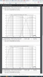
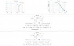
Then I started to simulate the values for Cs and Rs for a two-way-active-crossover.
I would use a 24dB/oct.- slope. Crossover-frequency at 2000 Hz.
And I had always the 'problem' in mind how to solve that roll-off in the upper frequency range
of the W16NX-001/8. Hmmm? 🤔
I made the following simulation with Mike Rothachers-calculator - ignoring the roll-off of the W16NX-001. Check pics.
Cheers
Dirk
Attachments
But how could we adress the problem with the roll-off of the MidBass?
Perhaps lowering the crossoverpoint of the lowpass in the 6-24AXO?
Any hints/tips are welcome! I am awaiting a good discussion. Let's have fun...
Cheers
Dirk 🤔
Perhaps lowering the crossoverpoint of the lowpass in the 6-24AXO?
Any hints/tips are welcome! I am awaiting a good discussion. Let's have fun...
Cheers
Dirk 🤔
Attachments

The sim looks like a good start, but in the end you will want to measure and/or listen to it and play around withe filter values.

Wow. Dirk, thank you so much for putting all this into a direct perspective for me. I am digesting all this information and will complete the board as described above. Speakers sound very good as they are now but I bet there are more to discover. I will post some pictures of the speakers.
Appreciate all your knowledge and enthusiasm for good audio.
Appreciate all your knowledge and enthusiasm for good audio.
Hello PC997,
you are welcome! But you know - there will be some homework left... 😉
A lot of listening and readjusting the filters ( I think especially the upper crossover frequency of the lowpass will have to be lowered?)
If you have questions - ask. I / We will try to help.
Adjust your trimpots before you solder them in. It is difficult / impossible to do this later.
Check every resistor with your DMM before you solder it in.
I hope you will be successful!
Have fun listening.
Cheers
Dirk 🙂
Yes.. Definitely Dirk..Hello PC997,
you are welcome! But you know - there will be some homework left... 😉
A lot of listening and readjusting the filters ( I think especially the upper crossover frequency of the lowpass will have to be lowered?)
If you have questions - ask. I / We will try to help.
Adjust your trimpots before you solder them in. It is difficult / impossible to do this later.
Check every resistor with your DMM before you solder it in.
I hope you will be successful!
Have fun listening.
Cheers
Dirk 🙂
Appreciate your help..
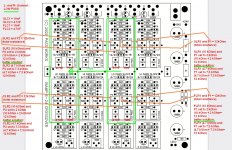
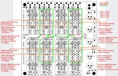
I am actually stuffing my 6/24 board, but I have three questions. Look at the image:

1. The value 221K is printed, but it should be a 1MEG resistor. Correct?
2. I cannot find these caps in the schematics. Whats the purpose? /Edit: I just see in the diyaudio Guide from 6L6: they are part of the PSU
3. These are the input caps, isn't it?
3a. In the schematics 0.1uF, Here some 10uF.
3b. is the polarisation on the PCB correct? + is connected to the 1MEG resistor to ground, minus to the potentiometers wiper connection?
Thanks for your support!
Franz
Last edited:
I am looking through this thread and I could find some more answers:
1. Post #180 mentionned 1MEG is correct
2. is already answered by the build guide from 6L6
3a. Post @171 Input caps
3b. not found up to now. I am quite sure the polarization is not correct when using electrolytics in this place
Franz
1. Post #180 mentionned 1MEG is correct
2. is already answered by the build guide from 6L6
3a. Post @171 Input caps
3b. not found up to now. I am quite sure the polarization is not correct when using electrolytics in this place
Franz
Hello Franz Gysi,
the input caps are 10uF (if you use polarized caps). The polarity of the input caps is correct on the pcb.
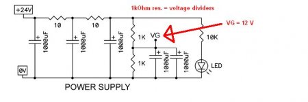
The 6-24-AXO is single ended. The music - signals '0 V - level' is shifted midway between ground and the +24 V rail (slightly below 12 V).
Cheers
Dirk
the input caps are 10uF (if you use polarized caps). The polarity of the input caps is correct on the pcb.
The 6-24-AXO is single ended. The music - signals '0 V - level' is shifted midway between ground and the +24 V rail (slightly below 12 V).
Cheers
Dirk
Ahh, thanks!
Now I understand it this way:
Now I understand it this way:
- VG in the PSU schematics is the Virtual Ground
- VG is connected to the VREF points in the main schematics
Hello Franz,
you are right.
I wish you a successful build and enjoy this fantastic active crossover!


Cheers
Dirk 😉
you are right.
I wish you a successful build and enjoy this fantastic active crossover!
Cheers
Dirk 😉
The bias resistor on Q2 sets the current to a value lower than Idss of the fet. It is optional. The bias resistor for Q1 is optional and only trims the DC setting. If I revise the board in the future I will probably drop the Q1 resistor and also replace the Q2 with the much less expensive J113 or similar.When using the Toshiba 2SK170's in the buffers, is a bias resistor used?
- Home
- Amplifiers
- Pass Labs
- DIY biamp 6-24 crossover