Hi Augerpro,BTW I think this claim by a single person that 1.2x wavelength is the best distance is gigantic oversimplification that will lead many down the wrong path. This claim needs to be backed up by an actual sim that we can all examine the assumptions so we can understand what we are even talking about.
I too remember reading this (perhaps it was Kimmo's post). From what I recall, he suggested 1x to 1.2x the x-over frequency - and it seems to have some merit:
According to ErinsAudioCorner - the March Audio Sointuva was the best passive speaker he has measured to date (utilizing Klipple).
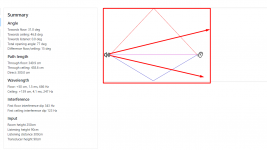
Looking at the measurements and the design, the c-t-c distance between the waveguide and mid appears to be approximately 175mm. The crossover frequency appears to be around 1,900Hz - 2,000Hz, corresponding to a wavelength of 181mm (at 1900hz) - 172mm (at 2000hz). <-- which matches the 1.0x recommendation. The Sound Power response is superb.
I would love to see if the measured repose further improves or degrades with an elliptical waveguide and lesser c-t-c distance.
Last edited:
dkalsi> look at the vertical polar, it has two very deep nulls just above and below the design axis. OTOH, this configuration might have improved the ceiling and floor bounce, improving the PIR and predicted score. But is it better this way? Do those nulls so close to the design axis cause a problem in typical usage? For example, you must always listen seated with the design axis exactly at ear height. Is that not a problem? I don't have answers to these questions, but my point is that there are unexamined assumptions in this claim, and they should be illustrated and debated.
To show why there is more nuance going on here, imagine two coincident sources with identical response. They combine to make one big lobe. Now start to move them apart vertically, the main lobe narrows, and somewhere off axis, 2 new ones appears. Keep moving them apart and the main lobe gets ever narrower, while ever more skinny lobes pop up off axis. Is this not a problem, or at least something to consider? Is it a good thing if a skinny main lobe, and a skinny ceiling and floor bounce lobe create a good PIR based on the CTA2034 rules, but as you move your head around you can hear the sound change because there so many skinny lobes?
Someone should start a thread investigating this, i don't want to wreck this one, but I'll participate in the new one. It would be best if Kimmo would do this, I asked him about this once and his answer included behavior at 90 degrees, which doesn't matter at all, and if you look over the CTA2034 rules is the lowest weighted angle of all of them. Perhaps at the end, I'll be on board the 1.2x bandwagon, but I feel as if everything else we know about lobing has been forgotten in this quest to game CTA2034 scoring.
Last edited:
The gigantic oversimplification comes from those re posting the information without understanding the content or reasons but remembering the specific numbers. There is plenty of information and examples to demonstrate the point. If the drivers are not able to be within 0.5 wl or less distance apart at the crossover frequency moving the distance out to between 1 and 1.4 wavelengths allows a smoother balance of early reflection and power response. This comes from the vertical null pattern and is a trade off.BTW I think this claim by a single person that 1.2x wavelength is the best distance is gigantic oversimplification that will lead many down the wrong path. This claim needs to be backed up by an actual sim that we can all examine the assumptions so we can understand what we are even talking about.
It at least makes sense to me that altering the inevitable lobing that comes from drivers vertically spaced towards a smoother early reflection response could have a positive effect and be the preferred compromise.
It is simple to test this in VituixCAD by using idealized drivers or existing measured data, moving the y value and crossover frequency up and down to see the effect on the complete radiation pattern.
Makes sense to me too in principle. It's the details that are being overlooked that trouble me. The improved PIR is dependent on the weighting of the floor and ceiling bounce angles the CTA committee selected. They look reasonable, but I know from a recent project where I had to calculate the actual angles of my room at the listening position, fell outside of the CTA2034 spec. If anything comes from this conversation, hopefully, it is that ideally you would use your actual room geometry to select the correct ctc distance.It at least makes sense to me that altering the inevitable lobing that comes from drivers vertically spaced towards a smoother early reflection response could have a positive effect and be the preferred compromise.
Yeah new thread for it would be nice.
Some numbers into calculator says at 3m listening distance ~10 degrees is about ~50cm, so small head movement while seated happens within few degrees and quickly simplifying people between 1m and 2m tall all have ears within 10 degrees when seated. Just keep the nulls outside of this, what ever is the application and requirements, and it should be fine.
The thing is, the sound that shoots to an angle between the first ceiling/floor reflection and ear take many boundary reflections before hitting the listening position making them into the room reverberant field and not to early reflections. Basically they would have come back all the way to front wall to get to listening position, maybe 3th order reflection. It would be great if the nulls can be pointed here, and it depends on everyones application.
Lets try an example, seated listening is the goal and +/-5 degrees for it is assumed to be fine for design axis, the main lobe. At 3m listening distance specular floor reflection might happen about 30 degree angle depending on the height of the drivers, ceiling reflection is at greater angle. Basically, point the nulls between 5-25 degrees, or perhaps to 15 degrees to make them out from not coloring direct or early reflections. I guess these angles are not in CTA2034 PIR calculation because they don't affect the perceived sound at listening position, hence making the graphs nice by pointing the nulls just below and above listening position would work nicely in reality as well, at least the reasoning seems logical. One should consider their own listening situation what the angles are, not too hard to calculate but missing from the discussion. Lets not forget the nulls are not 1 degree wide and could possibly reach out into both the listening window and the first reflection.
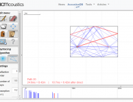
Attached is approximation of typical situation, if nulls shoot where the arrows are they would become at least 3rd order reflections. Change the parameters like listening distance or driver height and the situation changes. If listening distance gets shorter than this the angles toward first reflections get greater and less c-c spacing/ wider lobe works the same, or better since the 10 degree window at listening height is kept or preferably increased. Greater listening distance and it doesn't work anymore because the reflections happen at such low angle the null wouldn't fit between the floor and ear and in this case wider front lobe would work better, which could make null at greater angle and would make it perhaps to 2nd or 3rd order reflection between ceiling and floor.
edit. few more screenshots to show the low angle nulls would ideally make into 3rd order reflections. Very cool tool for this kind of experiments https://amcoustics.com/tools/amray
Some numbers into calculator says at 3m listening distance ~10 degrees is about ~50cm, so small head movement while seated happens within few degrees and quickly simplifying people between 1m and 2m tall all have ears within 10 degrees when seated. Just keep the nulls outside of this, what ever is the application and requirements, and it should be fine.
The thing is, the sound that shoots to an angle between the first ceiling/floor reflection and ear take many boundary reflections before hitting the listening position making them into the room reverberant field and not to early reflections. Basically they would have come back all the way to front wall to get to listening position, maybe 3th order reflection. It would be great if the nulls can be pointed here, and it depends on everyones application.
Lets try an example, seated listening is the goal and +/-5 degrees for it is assumed to be fine for design axis, the main lobe. At 3m listening distance specular floor reflection might happen about 30 degree angle depending on the height of the drivers, ceiling reflection is at greater angle. Basically, point the nulls between 5-25 degrees, or perhaps to 15 degrees to make them out from not coloring direct or early reflections. I guess these angles are not in CTA2034 PIR calculation because they don't affect the perceived sound at listening position, hence making the graphs nice by pointing the nulls just below and above listening position would work nicely in reality as well, at least the reasoning seems logical. One should consider their own listening situation what the angles are, not too hard to calculate but missing from the discussion. Lets not forget the nulls are not 1 degree wide and could possibly reach out into both the listening window and the first reflection.
Attached is approximation of typical situation, if nulls shoot where the arrows are they would become at least 3rd order reflections. Change the parameters like listening distance or driver height and the situation changes. If listening distance gets shorter than this the angles toward first reflections get greater and less c-c spacing/ wider lobe works the same, or better since the 10 degree window at listening height is kept or preferably increased. Greater listening distance and it doesn't work anymore because the reflections happen at such low angle the null wouldn't fit between the floor and ear and in this case wider front lobe would work better, which could make null at greater angle and would make it perhaps to 2nd or 3rd order reflection between ceiling and floor.
edit. few more screenshots to show the low angle nulls would ideally make into 3rd order reflections. Very cool tool for this kind of experiments https://amcoustics.com/tools/amray
Attachments
Last edited:
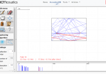
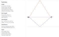
edit. for the above example of 3m listening distance, ~90cm heights of speaker and listener tweeter at listening height. Here is VCAD demonstration.
Let's see if the null can be fit between listening window and floor reflection. Look at the bottom right graph which is 0-40 vertical angles towards floor. The reflection in our scenario is at 30 degrees (blue line) and direct sound is 0 degree (red). We'd want the null to happen with the 10-20 degrees lines (green and yellow), more to the 20 than 10 if possible. From this experiment it looks like we barely make it, and it and it takes 2wl c-c! Ideally all red, yellow and blue lines would look the same. 0.5wl and 0.75wl here looks better than the 1.4wl for example, considering just the floor reflection.


From this experiment increasing c-c works better for short listening distances, less than 3m, as the angle towards floor reflection is greater and the null fits into window between the reflection and direct sound. However, angle towards ceiling is always bigger so that would work fine before floor which is the hard case.
If one imagines the situation by thinking size of the main lobe and moving the listener around it is quite easy to see that as the main lobe narrows the more the optimal listening position is constrained (vertically) but also by the distance especially with some height variance. If it is a bookshelf speaker and both the speaker and listener could be at any height or distance out of designers control then it would make more sense to go for biggest main lobe, least c-c spacing, coaxial/point source being the best.
Well, these things can be reasoned from many perspectives and it really is application dependent what kind of system works better.
Let's see if the null can be fit between listening window and floor reflection. Look at the bottom right graph which is 0-40 vertical angles towards floor. The reflection in our scenario is at 30 degrees (blue line) and direct sound is 0 degree (red). We'd want the null to happen with the 10-20 degrees lines (green and yellow), more to the 20 than 10 if possible. From this experiment it looks like we barely make it, and it and it takes 2wl c-c! Ideally all red, yellow and blue lines would look the same. 0.5wl and 0.75wl here looks better than the 1.4wl for example, considering just the floor reflection.
From this experiment increasing c-c works better for short listening distances, less than 3m, as the angle towards floor reflection is greater and the null fits into window between the reflection and direct sound. However, angle towards ceiling is always bigger so that would work fine before floor which is the hard case.
If one imagines the situation by thinking size of the main lobe and moving the listener around it is quite easy to see that as the main lobe narrows the more the optimal listening position is constrained (vertically) but also by the distance especially with some height variance. If it is a bookshelf speaker and both the speaker and listener could be at any height or distance out of designers control then it would make more sense to go for biggest main lobe, least c-c spacing, coaxial/point source being the best.
Well, these things can be reasoned from many perspectives and it really is application dependent what kind of system works better.
Attachments
Last edited:
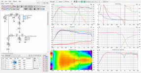
And for completeness sake one more. In the previous post tweeter was kept at listening height and woofer lowered increasing the c-c. Tried to change the height of the system instead and see if the null was just poorly positioned. With 1.4wl spacing it gets a bit better as it should as the null gets better fit between by manipulating the height of the system. But the null is just too big/wide to fit comfortably into the small window between 0-30 degrees.


While I'm not sure how much particular crossover topology affects here and what actually sounds better it looks like the nulls need to be made as small (tight angle span ) as possible in order this c-c trick to work out as touted. With 3m listening distance the 0-30 window is just very small to fit the null into.
Alright, if we decrease listening distance to 2 meters, the floor reflection is at ~40 degree angle which increases our shoot window roughly into 0-40 degrees, in which case we just look the purple line on the graphs instead of the blue one. Red, yellow and purple should be as similar as possible while the null should be on the blue and green lines. With 2m listening distance the 1.2wl or 1.4wl c-c for works nicely, better than 0.5wl for example. Just see the graphs posted on the previous post.
To recap my thoughts on the experiment: the increased c-c makes DI look nicer but does not help much with the first reflection if the angle to the reflection (floor) is small. Fitting a null into a small angle between listener and reflection is possible increasing c-c distance but this also makes the main lobe increasingly narrow. It looks like adjusting c-c suits nicely relatively short listening distances where angle towards first reflection is > 40 degrees where as at 3m and longer listening distance it makes more sense to use biggest lobe possible, smallest c-c. However, not knowing how these scenarios actually sound and that ceiling reflection is at greater angle even at 3m listening distance I cannot say which is actually better. It is great relief though, for builder, to know that there is no necessity to cram everything very close and roughly similar performance can be had with increased c-c especially if there are other compromises that would benefit doing this.
edit. sorry on the previous post forgot to insert the 1.4wl image between the others. Be sure to check the filename as you cycle through the attachments.
Attachments
Last edited:
I have made report to moderators if they would move my posts #1046-1048 to https://www.diyaudio.com/community/threads/vituixcad-simulations-with-ideal-drivers.380658/ as there is no new topic yet.
This was so interesting for the moment so couldn't help posting it out before thinking too much where it should belong
This was so interesting for the moment so couldn't help posting it out before thinking too much where it should belong
As an example of how this could apply to a situation using augerpro's waveguide and a small woofer. I don't know the correct dimensions but if the CTC distance ended up being 95mm (which looks like it could be for a 5" woofer and guide) by putting them as close together as could be that would be 0.7 wavelengths at 2500Hz. This combination of frequency and distance creates the worst of all outcomes, no smoothing of directivity and still a lot of vertical nulling. To push under 0.5 wavelengths with the tight spacing the crossover needs to be below 1800Hz.
This - sorry if some thought I was just "spitting out numbers that I had read somewhere sometime" - Fluid put to paper what I wasn't confident enough to spit out. I had in fact done simulations with "ideal" drivers in vituixCAD, and seen the evenness in soundpower by stretching out the CTC. But yes, it is a simulation only. I will have the ability to test both scenarios (closer 0.8x XO wavelength vs 1.2 XO wavelength CTC) soon. The difficulty being that it is vertical measurements which requires a bit more work to the turntable setup etc. But it will be worthwhile testing.The gigantic oversimplification ...
If you had a round waveguide you could just fudge it with VituixThe difficulty being that it is vertical measurements which requires a bit more work to the turntable setup etc. But it will be worthwhile testing.
I was floating the ideas of testing;
sb26 in 6.5 elliptical waveguide to 6.5 woofer - 140mm CTC - 2khz XO vs
sb26 in 6.5 elliptical waveguide to 6.5 woofer - 205mm CTC - 2khz XO vs
sb26 in 6.5 round waveguide to 6.5 woofer - 205mm CTC - 2khz XO.
Would the round waveguide matching the woofers directivity on the vertical axis make a difference and if so, how much?
Not to take anything away from the work done on the waveguides so far, I think they're amazing, I've got 4 of them. I'd just like to see for myself what the differences might be. I will be able to test the top two soon, hopefully I will get some actual findings and data to back up the "1.2x XO CTC" claim.
Stepping away from the objective for just a second, one thing that resonated with me was the suggestion that commercial 2 way stand-mounts have for pretty-much-ever not had the tweeters jammed up hard against the woofers, and that landscape doesn't seem to have changed. I'd tend to agree with that.
I'm thinking mainly sound power, not DI's or PIR's. And I'm keeping on topic of waveguides, hence why I didn't think to start a thread, but yes a dedicated thread for CTC if I get interesting findings.
Last edited:
The DI of a round waveguide should be a better match to the vertical of a round woofer but the best profile for a round waveguide may not be the same as it is for the horizontal part of an elliptical one.Would the round waveguide matching the woofers directivity on the vertical axis make a difference and if so, how much?
A round version can be made from the step files
^^ Yeah even though the power and DI and PIR come smoother with increased c-c spacing, null at smaller angle, they do so partly how the power is calculated so all this is kind of vague in that sense I think, what augerpro refers as what CTA commitee chose to use? My examples considers only the effect on first reflection response never minding what the power or PIR eventually would be, and there is not many if at all comments what actually sounds better. But as demonstrated the angle and spectrum of first reflections change with changing listening position even though the calculated power and DI (output of the speaker) stays the same. Hence the suspicion I believe.
Attached is weights from CTA2034 used for power calculation with 10 deg measurement steps. As null is moved from ~40deg to ~20deg and is made "narrower" the weighting halves and partly smoothens the power just by that. One could still listen at the nulls even if the power was smooth. Perhaps they are wisely chosen weights? I'm not exactly sure if this is just a technical thing that needs to be taken account or something that would actually make some angle more important than some other. Weights (angles) on the PIR calculation is another thing, which I can't currently find what those were.

Attached is weights from CTA2034 used for power calculation with 10 deg measurement steps. As null is moved from ~40deg to ~20deg and is made "narrower" the weighting halves and partly smoothens the power just by that. One could still listen at the nulls even if the power was smooth. Perhaps they are wisely chosen weights? I'm not exactly sure if this is just a technical thing that needs to be taken account or something that would actually make some angle more important than some other. Weights (angles) on the PIR calculation is another thing, which I can't currently find what those were.
Last edited:
Dang edit time over, pardon:
Edit: Yeah the power weights are just technical thing like fluid points out in the next post. PIR includes some particular angles (average of several). This reads in CTA2034-A standard page 54:
"
Sound power represents all of the sounds arriving at the listening position after any
number of reflections from any direction. It is the weighted rms average of all 70
measurements, with individual measurements weighted according to the portion of the
spherical surface that they represent. Sound power is a measure of the total acoustical
energy radiating through an imaginary spherical surface with the radius equal to the
measurement distance. Thus the on-axis curve has very low weighting because it is in
the middle of other closely adjacent measurement points (see the perspective sketch at
the top of Figure 1) and measurements further off axis have higher weighting because of
the larger surface area that is represented by each of those measurements. Ideally, such
a measurement would be made at equally-spaced points on the entire surface of the
sphere, but this simplified spatial-sampling process turns out to be a very good
approximation. The result could be expressed in acoustic watts, the true measure of
sound power, but for the purposes of this standard it is expressed as sound level, a
frequency response curve having the same shape. Any bump in the curve that shows
up in the other curves (on-axis, early reflections, etc.) and persists through this ultimate
spatial average is a notable resonance. Calculation of the sound power curve begins with a
conversion from dB to a scalar magnitude. The individual measures of sound pressure
are then weighted according to the values shown in Appendix C and an energy average (rms)
is calculated using the weighted values. The final average is converted to dB.
"
And
"
Vertical reflections. The “floor reflection” is defined as the spatial average of three measurements at 30 degrees below the main-axis ± 10 degrees. The “ceiling reflection” is defined as the spatial average of three measurements at 50 degrees above the mainaxis ± 10 degrees.
"
So I suspect that as the c-c increases the more and narrow lobes happen but also nulls get narrower. At particular situation the nulls just have smaller portion of angle pie than the lobes combined and DI smoothens.
It is quite clear to me that it would make sense to transfer the contribution of a null from early reflection to late reverberation if at all possible. Also it makes sense not to introduce the nulls into listening window no matter what.
Last edited:
I think there is some confusion here. The soundpower is weighted by the portion of a sphere that the measurement represents, this is not specific to CTA2034.^^ Yeah even though the power and DI and PIR come smoother with increased c-c spacing, null at smaller angle, they do so partly how the power is calculated so all this is kind of vague in that sense I think, what augerpro refers as what CTA commitee chose to use?
The early reflection angles came out of a Devantier study on various different rooms, being an average there will be cases where it not entirely representative for a specific layout.
Are many of these issues more of a theoretical type, rather than a real problem/challenge to be dealt with?
Because when I sit and listen now - I really have to struggle to find problems with the sound in any type of music with either strings, bells, horns, female S's, piano or anything like it, except in the woofer range between 80-500Hz, where a very slight room induced resonance can be heard in some tracks.
The combo of a 5" midrange and the 5" oval waveguide, works like something I have very rarely heard anywhere - no matter the price. It's exceptional clear, detailed and the phantom image is dead center and very focused - like I'm not even thinking about the speakers - sound just seems to emanate from a fictive speaker between the speakers - when the music is made to fit this illusion of course. Some music makes the sound almost come from a source to the side of me.
So what are your references or maybe specific tracks, that make you want more or miss something? - If this i not too much OT.
- Home
- Loudspeakers
- Multi-Way
- Open source Waveguides for CNC & 3D printing!