The only thing I've been using for a few years now is a slightly modified TPA3116 budget board (I don't listen to music at home often). I wasn't unhappy with the sound in the least, but without a direct A/B comparison, I can't really comment on how the two amps compare. I only bought this amp for a fun project and because the TPA board never even found its way into a case; just a bare board collecting dust behind my entertainment center.Ah it is not the worst either. How does the amplifier with the modifications compare with other amplifiers you have?
I might go down the rabbit hole of using a DigiSpark (Attiny85) to write the settings I want. I already have one that I used for the most basic task of blinking an LED at a specific frequency a long time ago. I think TinyWireM is the Arduino library needed to accomplish the goal. I know it's going to take me countless hours to learn the code needed to simply write the two bytes of data I need changed.
Aslo, I forgot to mention that even after my filter mods and changing to different power modes via I2C, the amp still has that strange switching noise. I think it's coming from the inductors. I'm wondering if it's from the way the board is laid out for the dual inductors. The input/outputs of the inductor pairs are diagonal, perhaps causing them to "fight" each other?
Last edited:
Sorry to bugger up this thread with my idiotic musings, but I've made a little progress. I forgot I have an UNO I used a single time to flash a bootloader on a 3D printer. I turned it into a logic analyzer and was able to see the DigiSpark trying to communicate with the slave (not connected). I'm confused why the I2C Analysis results window shows the address as 0x40 and in the main program window shows "Setup write to slave: 0x20 [0x40]". So which is it, 0x20 or 0x40?
Attachments

Congratulations! Here's hoping the experience benefits your resume in a meaningful way, one day.
Finally completed my MA12070P (i2s version) amp. My first SMD design and build. Thanks to similar projects by matt_garman and Fabianmu in convincing me that QFN packages can indeed be soldered at home with a bit of practice.


I'm running it at 24v and works fine. All my SMD MLCC caps are rated 50v to take into account any degradation of capacitance due to voltage biasing.
The amp is quiet. I implemented the output filter with a 1.5uH inductor as recommended by Infineon. I took a chance with the lowest recommended inductance since I could get a decent 30A saturation current rating without a monster sized inductor. At least I know that the output currents are far from saturation and the filter is operating in the linear area of the inductor.
The board also has space for input film caps when I build the analog version later
So far liking the sound. Either its my imagination, but there is a 3D like sound, perhaps better imaging? I'll do some A/B testing at a later date. The efficiency of the amp is as advertised and the chip gets just warm while the inductors remain cold even when pushed hard. I won't bother with a heatsink for this one.
The only issue I face is in the software side. Some bugs with the volume control via I2C. Like theAnonymous, I'm not a software person and will probably take longer than most to iron it out.
Last edited:
The only thing I've been using for a few years now is a slightly modified TPA3116 budget board (I don't listen to music at home often). I wasn't unhappy with the sound in the least, but without a direct A/B comparison, I can't really comment on how the two amps compare. I only bought this amp for a fun project and because the TPA board never even found its way into a case; just a bare board collecting dust behind my entertainment center.
I might go down the rabbit hole of using a DigiSpark (Attiny85) to write the settings I want. I already have one that I used for the most basic task of blinking an LED at a specific frequency a long time ago. I think TinyWireM is the Arduino library needed to accomplish the goal. I know it's going to take me countless hours to learn the code needed to simply write the two bytes of data I need changed.
Aslo, I forgot to mention that even after my filter mods and changing to different power modes via I2C, the amp still has that strange switching noise. I think it's coming from the inductors. I'm wondering if it's from the way the board is laid out for the dual inductors. The input/outputs of the inductor pairs are diagonal, perhaps causing them to "fight" each other?
The MA12070 needs two supplies, 5v to power the internal signal processing and a higher voltage for the amp. I found the chip sensitive to noisy 5v supplies, resulting in noise in the output.
I did not incorporate a 5v step down on my board, so during testing, I simply tapped 5v from the Raspberry Pi which is not known to be quiet. This resulted in a noisy output. More like an interference beat noise when two different frequencies mash up.
When I swapped it for a quieter source and filtered with my on board LDO, it all went quiet.
On the other hand, the amp is quite robust when it comes to the main voltage feed. I've thrown my noisiest power supply at it and it's still quiet.
Last edited:
Finally completed my MA12070P (i2s version) amp. My first SMD design and build. Thanks to similar projects by matt_garman and Fabianmu in convincing me that QFN packages can indeed be soldered at home with a bit of practice.
View attachment 1041762
View attachment 1041763
View attachment 1041764
I'm running it at 24v and works fine. All my SMD MLCC caps are rated 50v to take into account any degradation of capacitance due to voltage biasing.
The amp is quiet. I implemented the output filter with a 1.5uH inductor as recommended by Infineon. I took a chance with the lowest recommended inductance since I could get a decent 30A saturation current rating without a monster sized inductor. At least I know that the output currents are far from saturation and the filter is operating in the linear area of the inductor.
The board also has space for input film caps when I build the analog version later
So far liking the sound. Either its my imagination, but there is a 3D like sound, perhaps better imaging? I'll do some A/B testing at a later date. The efficiency of the amp is as advertised and the chip gets just warm while the inductors remain cold even when pushed hard. I won't bother with a heatsink for this one.
The only issue I face is in the software side. Some bugs with the volume control via I2C. Like theAnonymous, I'm not a software person and will probably take longer than most to iron it out.
Hello.
The Topping PA3s has no output inductors and works great. The protection doesn't work.
Try turning off the inductors, your experience is interesting.
Yes the sound of the MA12070 is 3D like any good amplifier should have.So far liking the sound. Either its my imagination, but there is a 3D like sound, perhaps better imaging? I'll do some A/B testing at a later date. The efficiency of the amp is as advertised and the chip gets just warm while the inductors remain cold even when pushed hard. I won't bother with a heatsink for this one
Simply...well done!!!Finally completed my MA12070P (i2s version) amp. My first SMD design and build. Thanks to similar projects by matt_garman and Fabianmu in convincing me that QFN packages can indeed be soldered at home with a bit of practice.
View attachment 1041762
View attachment 1041763
View attachment 1041764
I'm running it at 24v and works fine. All my SMD MLCC caps are rated 50v to take into account any degradation of capacitance due to voltage biasing.
The amp is quiet. I implemented the output filter with a 1.5uH inductor as recommended by Infineon. I took a chance with the lowest recommended inductance since I could get a decent 30A saturation current rating without a monster sized inductor. At least I know that the output currents are far from saturation and the filter is operating in the linear area of the inductor.
The board also has space for input film caps when I build the analog version later
So far liking the sound. Either its my imagination, but there is a 3D like sound, perhaps better imaging? I'll do some A/B testing at a later date. The efficiency of the amp is as advertised and the chip gets just warm while the inductors remain cold even when pushed hard. I won't bother with a heatsink for this one.
The only issue I face is in the software side. Some bugs with the volume control via I2C. Like theAnonymous, I'm not a software person and will probably take longer than most to iron it out.
I love this infineon chip!
@altus fidelitas - your amp looks great! Thanks for sharing!
Would you mind sharing what technique you used and found successful? I do have a working PCB I made quite a while ago, it's been running 24/7 with no issues. But I also had a few failed attempts at soldering that ma12070p QFN package, so I've been hesitant to revisit this project.
Are you manually sending the I2C commands to the chip? I see you're using a Raspberry Pi. Assuming you're using some flavor of Linux, there are Infineon-authored MA12070P ALSA drivers. When I first started playing with this chip I was manually sending I2C commands... but once I realized the drivers exist, the software part became more or less plug-n-play: the chip is recognized by the driver, and essentially looks like any other audio device in Linux. Not only that, but most of the controls are exposed by the driver and can be tweaked with the "alsamixer" program.
in convincing me that QFN packages can indeed be soldered at home with a bit of practice.
Would you mind sharing what technique you used and found successful? I do have a working PCB I made quite a while ago, it's been running 24/7 with no issues. But I also had a few failed attempts at soldering that ma12070p QFN package, so I've been hesitant to revisit this project.
The only issue I face is in the software side. Some bugs with the volume control via I2C. Like theAnonymous, I'm not a software person and will probably take longer than most to iron it out.
Are you manually sending the I2C commands to the chip? I see you're using a Raspberry Pi. Assuming you're using some flavor of Linux, there are Infineon-authored MA12070P ALSA drivers. When I first started playing with this chip I was manually sending I2C commands... but once I realized the drivers exist, the software part became more or less plug-n-play: the chip is recognized by the driver, and essentially looks like any other audio device in Linux. Not only that, but most of the controls are exposed by the driver and can be tweaked with the "alsamixer" program.
Would you mind sharing what technique you used and found successful? I do have a working PCB I made quite a while ago, it's been running 24/7 with no issues. But I also had a few failed attempts at soldering that ma12070p QFN package, so I've been hesitant to revisit this project.
You need much less solder paste than you actually think you need.
When practicing, I found that anything more than a smear of solder paste on the centre pad will cause the package to float. As a result, only one side of the QFN will contact the board properly, with the blob of solder in the centre pad acting as a pivot. I compensated for the opposite 'high side' by putting more solder, but it also caused bridges.
So when actually soldering the MA12070, I smeared the thinnest possible layer of solder paste on the centre pad, and the thinnest line of paste I could apply with a syringe across all the pins.
After reflowing, I applied liquid flux across on all four sides and with a clean chisel tip iron, melted the solder and pulled from the chip outwards. Again, make sure the iron tip is clean, as you don't want to introduce additional solder when cleaning up bridges.
I read somewhere that even a 50% thermal pad contact to PCB is sufficient for effective heat transfer. So I would prioritize the chip being flat on the board over 100% solder contact when applying paste. Any vias on the PCB thermal pad would of course help in wicking any excess solder.
And now that the MA12070 has proven that it runs cool, I'm not so concerned about getting the centre pad 100% soldered
BTW, I also looked at your circuit diagram and you have got your pin 60 and 61 swapped
I'm a NOOB when I comes to programming....anything. I just found out that ALSA means Advanced Linux Sound Architecture, so I must be running Linux 🤔Are you manually sending the I2C commands to the chip? I see you're using a Raspberry Pi. Assuming you're using some flavor of Linux, there are Infineon-authored MA12070P ALSA drivers.
I've been using Volumio for a while now and love it. So when I saw Infineon had a Merus HAT and driver for Volumio, I jumped at it.
The driver works fine most of the time. However, even at zero volume on Volumio, music still plays softly. Theoretically, there should be silence at zero volume, esp with hardware volume control.
The problem is when I use the Spotify connect plugin. Zero volume seems to be somewhere 5% up the volume slider on the app. But slide the volume anything less than that, it goes to FULL volume. Other users at home may not appreciate this 'hidden' feature.
I did notice that the compiled DT overlays with .dtbo have not been maintained for a while. Is there a possibly that the current DT overlay has not been updated for the latest kernels?
👍My first SMD design and build.
I recently played with an "outboard" output filter - air core, point to point wiring inside a non-ferrous metal Hammond box. Got some EMI as received by a nearby (on top of) AM radio. Actually decodes and plays music!
Having no idea if this was big or small, I connected up an el-cheapo Chinese USB/BT/AUX IN class D amp - with no visible output inductors, save some little 0603 / 0805 jobs that "must be it". That amp radiated far more strongly than my outboard setup!
I'd say in general EMI goes up with reduction of output filter inductance. In order to make the outboard connection, I had to ruin another cheap ebay class D amp by ripping off the output inductors (20mH) and some of the etch with it, all the output caps on board. Jumping the inductors with a wire, it works with 18 mH aircores and .33uf caps.
This was to try the idea in anticipation of doing such to my Zoudio amp. There's really not enough room to do such ops in either amp, but I tried and got it to work, first using the more disposable of the two.
There isn't any noise audible through the speakers, just the output inductors. They don't get warm and it doesn't seem to be causing any real problems, so I'll just live with. I tried putting extra filtering (3uH inductor + 220uF) on the output of the XL1509 like recommended in its datasheet, but no change in the inductor noise.The MA12070 needs two supplies, 5v to power the internal signal processing and a higher voltage for the amp. I found the chip sensitive to noisy 5v supplies, resulting in noise in the output.
I did not incorporate a 5v step down on my board, so during testing, I simply tapped 5v from the Raspberry Pi which is not known to be quiet. This resulted in a noisy output. More like an interference beat noise when two different frequencies mash up.
When I swapped it for a quieter source and filtered with my on board LDO, it all went quiet.
On the other hand, the amp is quite robust when it comes to the main voltage feed. I've thrown my noisiest power supply at it and it's still quiet.
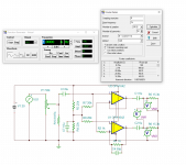
I think I'm done modding this BRZ HiFi amp now. Made more changes to the input circuit. Changed the feedback resistors on the inverting half of the OPA1642 to 1k/1k instead of 10k/10k and connected the inverting input to the output of the non-inverting side. Changed the biasing resistors so now the circuit has a 20k input impedance in parallel with an 8.87k resistor to "law fake" the 50k linear taper pot.
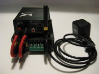
The DigiSpark is permanently wired in now and I added a small USB-C cable that's connected to the internal 5V supply to power the bluetooth DAC. Now I can use the tiny 65W GaN adapter to power it all instead of using two power adapters.
Maybe now I can try and get back into listening to music again.
Attachments

Hello theAnonymous1,There isn't any noise audible through the speakers, just the output inductors. They don't get warm and it doesn't seem to be causing any real problems, so I'll just live with. I tried putting extra filtering (3uH inductor + 220uF) on the output of the XL1509 like recommended in its datasheet, but no change in the inductor noise.
I think I'm done modding this BRZ HiFi amp now. Made more changes to the input circuit. Changed the feedback resistors on the inverting half of the OPA1642 to 1k/1k instead of 10k/10k and connected the inverting input to the output of the non-inverting side. Changed the biasing resistors so now the circuit has a 20k input impedance in parallel with an 8.87k resistor to "law fake" the 50k linear taper pot.
The DigiSpark is permanently wired in now and I added a small USB-C cable that's connected to the internal 5V supply to power the bluetooth DAC. Now I can use the tiny 65W GaN adapter to power it all instead of using two power adapters.
Maybe now I can try and get back into listening to music again.
What is your listening impression after these mods? You preferred it over the TPA boards ?
I am also planning to buy the board to play
Thanks
I don't have any complaints about the sound. My memory is really bad (I've had three serious concussions) and it's been some time since I listened to the TPA so I can't say if it's better, worse, or just different.Hello theAnonymous1,
What is your listening impression after these mods? You preferred it over the TPA boards ?
I am also planning to buy the board to play
Thanks
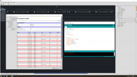
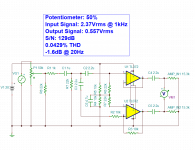
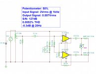
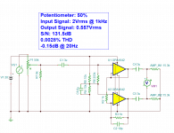
Someone pointed out to me that I had the bias implementation wrong, so I made even more changes since last post. The attached pictures show the original input circuit, the circuit with slight mods that leave the original cap values, and then the same mods + cap value changes and OPA1642 swap. The input level was raised on the original circuit to match the output on the other two. I noticed there was increased noise with my ear next to the tweeter with the pot at around 50% on the original circuit, which is entirely gone now.
Attachments
Hs anyone tried this BRZHIFI M6?
https://www.aliexpress.com/item/100...52.9;-1;14.29@salePrice;DKK;search-mainSearch
https://www.aliexpress.com/item/100...52.9;-1;14.29@salePrice;DKK;search-mainSearch
That was a lie. Even though I couldn't hear the noise from my listening position, the fact that it was there at all was really bothering me, because it shouldn't be there.There isn't any noise audible through the speakers, just the output inductors. They don't get warm and it doesn't seem to be causing any real problems, so I'll just live with...
I had a long think about it and decided to try replacing the output flying caps. The originals were probably 25VDC X5R, two parallel 10uF per output node to account for DC bias capacitance loss. I replaced them with one piece 10uF 75VDC X7R per output node.
With the cover off and my ear pressed right against the board, I don't hear anything at all now. Before I could hear it with the cover on from a foot or two away.
- Home
- Amplifiers
- Class D
- Infineon MA12070 Class D