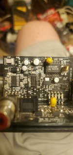
Perry, so I tested the voltages and same thing....I took two newer comparators that had matching date codes off an old little rf amp, and soldered them two the card. This time I actually took the card out to solder to it.Yes, repost the voltages you currently have.
Contact Rockford to see if you can get the diagrams for the amp.
Now I'm getting a fast clicking. .I then just hooked the remote up to power and used just the ground to connect the circuit. A bunch of times, each time it sounded a lil different.
Voulla.
Solid blue light no protect!
Thank you perry your the ****!
Awesome..you are the man....
Ok, now can you teach me how to listen to the square waves of the ps fets.. I promise I will send u a lil dough, when we are through.
I hope people in the past have donated to you..
I have the scope ready and after just reading that page you sent me like 2 or 3 times. Then I just thought about the definitions of the adjustments and the scope just made sense and wasn't overwhelming anymore..
it's really simple actually ..Thanks again ready when you are..
You likely struggled getting the driver board out if you didn't have low-temperature solder. Look up ChipQuik if you're not familiar with it.
What do you need to know about the square wave signals on the PS FETs?
If you're willing to spend anything on this hobby, you may be interested in my amplifier repair tutorial. The basic repair page (page 20 on the site below) is a good start if you haven't read it.
http://www.bcae1.com
What do you need to know about the square wave signals on the PS FETs?
If you're willing to spend anything on this hobby, you may be interested in my amplifier repair tutorial. The basic repair page (page 20 on the site below) is a good start if you haven't read it.
http://www.bcae1.com
U100You likely struggled getting the driver board out if you didn't have low-temperature solder. Look up ChipQuik if you're not familiar with it.
What do you need to know about the square wave signals on the PS FETs?
If you're willing to spend anything on this hobby, you may be interested in my amplifier repair tutorial. The basic repair page (page 20 on the site below) is a good start if you haven't read it.
http://www.bcae1.com
1. 0.03v
2. 0.04v
3. 12.45v
4. 5.95v jumps around
5. 1.34v
6. 2.46v
7. 1.63v
8. 4.07v
9. 2.12v
10. 0.27v
11. 1.13v
12. 0.0v
13. 7.99-8.25v
14. 0 .15v
If I short Pin 2 and 3 (12v and output 2 the blue light becomes solid) no protect...
U101
1. 0.04v
2. 3.0-3.05v
3. 12.45v
4. 0.19v
5. 1.96v
6. 5.91-6v
7. 1.34v
8. 3.85v
9. 4.97v
10. 4.97v
11. 7.31v
12. 0.0v
13. 2.59v
14. 2.58v
Thank you perry..lemme know
I haven't taken the driver card out yet..this 2500.1bd has a power supply card that has the comparators and mcu controlling the oscillation for the powersupply fets on a card that's removable like a driver card.. if you wernt aware
In the 2500s that I saw, the driver boards were soldered in.
What's the part number of the MCU in that amp?
Did you try to get the diagrams for this amp from Rockford?
What's the part number of the MCU in that amp?
Did you try to get the diagrams for this amp from Rockford?
I'm still trying to get the schematics.In the 2500s that I saw, the driver boards were soldered in.
What's the part number of the MCU in that amp?
Did you try to get the diagrams for this amp from Rockford?
Attachments
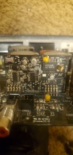
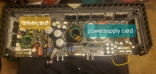
Both the boards in the center photo are driver boards/cards. One is for the power supply The other is for the class D audio section.
There is no MCU on that power supply driver board. The driver IC (UC3526) is an analog IC.
There is no MCU on that power supply driver board. The driver IC (UC3526) is an analog IC.
Didn't realize I was using bad terminology. I really didn't even look at the chip either. I just called it that because it had a **** ton of pins and is big.. figured it was... my bad. I guess they both drive the fets right? Or they drive another transister that drive the fets correct?Both the boards in the center photo are driver boards/cards. One is for the power supply The other is for the class D audio section.
There is no MCU on that power supply driver board. The driver IC (UC3526) is an analog IC.
I thought driver and thought output stage ..I'm learning... thank you though. I really hope rf gives me the service manual or schematic
They generate the signals that will eventually drive the FETs.
Attached is the diagram of the main board that has been posted on the forum, previously. You can see what the driver boards drive through before the FETs.
Attached is the diagram of the main board that has been posted on the forum, previously. You can see what the driver boards drive through before the FETs.
Attachments
I'm super confused though what is making it go into protect still?They generate the signals that will eventually drive the FETs.
Attached is the diagram of the main board that has been posted on the forum, previously. You can see what the driver boards drive through before the FETs.
Like I said if I bridge 12v power and output 2 of the comparator u100, the blue light goes solid. so can that tell me that output 2 needs to be higher? or is that backfeeding voltage back through some how? ..I'm sorry for the dumb question...
Yeah they denied me .I asked again ...we will see. The one you sent me from a previous post they didn't have the driver cards to post?
The driver boards were not posted.
There is something wrong.
U100 is the SG3526 and it has 18 pins.
Re-check the circuit board designations for the two ICs that you posted the voltages for.
There is something wrong.
U100 is the SG3526 and it has 18 pins.
Re-check the circuit board designations for the two ICs that you posted the voltages for.
I
Sorry u101 and u102 my badThe driver boards were not posted.
There is something wrong.
U100 is the SG3526 and it has 18 pins.
Re-check the circuit board designations for the two ICs that you posted the voltages for.
Attachments
Which one above is actually 101 and which is 102? Copy and paste the two lists below with correct the designations.
The one I said was 100 is 101 and 101 is 102Which one above is actually 101 and which is 102? Copy and paste the two lists below with correct the designations.
U101Which one above is actually 101 and which is 102? Copy and paste the two lists below with correct the designations.
1. 0.03v
2. 0.04v
3. 12.45v
4. 5.95v jumps around
5. 1.34v
6. 2.46v
7. 1.63v
8. 4.07v
9. 2.12v
10. 0.27v
11. 1.13v
12. 0.0v
13. 7.99-8.25v
14. 0 .15v
If I short Pin 2 and 3 (12v and output 2 the blue light becomes solid) no protect...
U102
1. 0.04v
2. 3.0-3.05v
3. 12.45v
4. 0.19v
5. 1.96v
6. 5.91-6v
7. 1.34v
8. 3.85v
9. 4.97v
10. 4.97v
11. 7.31v
12. 0.0v
13. 2.59v
14. 2.58v
Thank you perry..lemme know
I haven't taken the driver card out yet..this 2500.1bd has a power supply card that has the comparators and mcu controlling the oscillation for the powersupply fets on a card that's removable like a driver card.. if you wernt aware
What happened after post 61 where you got a blue LED lighting up that now prevents it from lighting up?
You had the designations of the comparators wrong. Which comparator did you replace?
Was the replacement new?
You had the designations of the comparators wrong. Which comparator did you replace?
Was the replacement new?
No they were not new they came off another rockford.. should they be? Are they not good to take off used? I replace bothWhat happened after post 61 where you got a blue LED lighting up that now prevents it from lighting up?
You had the designations of the comparators wrong. Which comparator did you replace?
Was the replacement new?
- Home
- General Interest
- Car Audio
- RF T2500.1BD