Did you use half symmetry as you have different top and bottom spacing? Leaving it at 1/4 could cause things to get wrapped in on each other.
1/4 symmetry is used and I think correctly.
I am under the impression than when 1/4 symmetry is used the Spacing can be declared as in the example given by Mabat here:
https://www.diyaudio.com/community/...he-easy-way-ath4.338806/page-481#post-6977507
And the first Spacing value is ignored, it is only possible to change the spacing on the top (and bottom by symmetry) :
https://www.diyaudio.com/community/...he-easy-way-ath4.338806/page-486#post-6985318
The control points are fine (you can set Mesh.Wireframe=1 and check the MSH file, see below), it's just that the surface (or the curve) is meshed with an extremely low resolution, despite the control points being defined correctly. This looks like a gmsh "thing" to me. Perhaps too high degree of the curve? (I would expect 4 - 6 points to be enough - remember this is not an interpolating curve.)

Last edited:
That's not connected in any way. For 1/4 symmetry simply only the 1st quadrant is generated, no matter what are the other spacing values.Did you use half symmetry as you have different top and bottom spacing?
Note that with 4 control points you can already create something quite similar (and it works fine): https://www.desmos.com/calculator/acaiukh1bv
box = {
point P0 103 0 5
point P1 180 5 10
point P2 80 135 12
point PB 0 137 16
bezier P0 P1 P2 PB
}


- That would be another option how to draw a waveguide.
box = {
point P0 103 0 5
point P1 180 5 10
point P2 80 135 12
point PB 0 137 16
bezier P0 P1 P2 PB
}
- That would be another option how to draw a waveguide.
Last edited:

Anyway, for Bezier curves the middle control points don't seem to affect the mesh resolution - something to be aware of.

Code:
box = {
  point P0    103       0      1
  point P1    180       5      1
  point P2    80        135    1
  point PB    0.0000    137    1
  bezier P0 P1 P2 PB
}...working hard 🙂
Once you have an enclosure code, you can place a copy anywhere you want -

Once you have an enclosure code, you can place a copy anywhere you want -
The amount of progress is incredible. This is what I was waiting for. Thanks @mabat!
Now I might have to buy a new computer first...
Now I might have to buy a new computer first...
It can help to optimize your process in ath, if you are optimizing by eye and not, as maiky76's matlab scripts do, by sheer brute force processing power.The amount of progress is incredible. This is what I was waiting for. Thanks @mabat!
Now I might have to buy a new computer first...
Once you have a desirable basic shape of your response, your raw material so to say, it is possible to optimize in steps, and then in sections, i. e. low frequencies, high frequencies etc.
1) For round or elliptical devices, first setting up a slope in circular symmetry mode proves to be a good starting point from where to procede to 3D.
2) Infinite baffle simulation is fine for mid to high frequencies. The slightly wider pattern that results from the infinite baffle from my experience was easily corrected with a slightly wider coverage angle.
3) I have found that between quarter symmetry and half symmetry, the differences are few, at least those which can be corrected (which the baffle bump cannot).
4) The resolution of the mesh for lower frequencies is also not required as high, as long as shape is not deteriorated significantly. Together with simulating frequency sections, this reduces simulation a lot. It is a bit more of typing but a good method is to have a couple of versions of the .cfg for all other parameters than the curve functions, and then just copy & paste these.
Got my automated ath generator up and running again, now with ESP 😀 Of course now there are even more parameters to consider...

Yes, as there's still the same spherical wavefront at the exit of the ESP (and the rest of the WG doesn't change), the directivity doesn't change. What we see on that gif is that the longer the shaping plug, the worse match for the rest of the waveguide it is. Something else on the horn side would need to be adjusted at the same time to reduce the increasing impedance peak.
I have exported a full sphere (+- 180 deg Hor & Ver) from VCAS and after renaming them from hand, imported them in VCad. But I don't see how i. e. Power response could be correct. It has only changed in level, but the further off-axis angles should tilt it. Does someone know why? I have attached a file as exported from VCAS.

Attachments
It can be deceiving, I believe it's correct. The far off-axis polars are tilted but they are also quite low in level.
Ouch! That’s dedication 🙂 For next time: https://docs.microsoft.com/en-us/windows/powertoys/powerrenameI have exported a full sphere (+- 180 deg Hor & Ver) from VCAS and after renaming them from hand
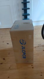
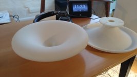
Got my WGs from JLCPCB. Looks and feels good (don't have any prior experience with printed stuff...) - seem sturdy as well as symmetrically correct i.e. rests flat on a flat surface.
Price was using their ordering page about 100€ inc shipping. In the end after some size and shipping restraints, it came to 150€ (for 2 pcs). OK i think.
Now a long wait for the BMS 5530ND CDs... :-/ which I plan to drive with a Topping L30 HP amp.
Thanks to mabat for sharing the design and pelanj for fixing the mounting holes in the 260-30 cad.
//
Attachments

Last edited:
These look pretty good! Can you make some detailed pictures of the surface texture? Both on the flange and the mouth?
- Home
- Loudspeakers
- Multi-Way
- Acoustic Horn Design – The Easy Way (Ath4)