Arcadia234,
1. Was this build from the diyAudio kit, with Q1, Q2, and R1 matched? What is the value of the R1 resistors? What is the voltage across each R1 (meter probe at each end of the resistor), (V1, V2, V5, V6)?
2. Did you measure the voltage at T5 and T6 and were they correct?
3. Did you adjust the pot in each channel to try to get 10V at T7 and T8?
4. What is the voltage across the 332k resistors (meter probe at each end of the resistor), (V3, V4)?
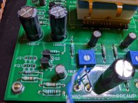
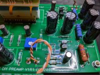
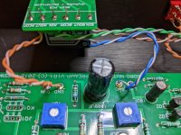
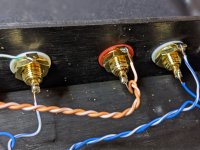
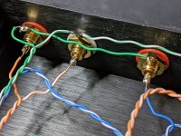
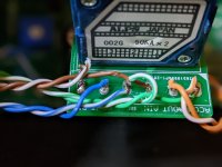
4. Post pictures that show the whole preamp, including wires to inputs, outputs, switches, volume control, and closer pictures of the board.
1. Was this build from the diyAudio kit, with Q1, Q2, and R1 matched? What is the value of the R1 resistors? What is the voltage across each R1 (meter probe at each end of the resistor), (V1, V2, V5, V6)?
2. Did you measure the voltage at T5 and T6 and were they correct?
3. Did you adjust the pot in each channel to try to get 10V at T7 and T8?
4. What is the voltage across the 332k resistors (meter probe at each end of the resistor), (V3, V4)?
4. Post pictures that show the whole preamp, including wires to inputs, outputs, switches, volume control, and closer pictures of the board.
Attachments

I'm happy to provide photos if you can tell me what you want to see.
Hi Arcadia,
You will definitely need to provide Hi-Res pictures so the electronic trouble-shooting GuRu's can help you further.
EDIT:
Ben Mah is here to help you....

Thanks for the assist, Ben. Glad to have you on board... Board! Get it?Arcadia234,
1. Was this build from the diyAudio kit, with Q1, Q2, and R1 matched? What is the value of the R1 resistors? What is the voltage across each R1 (meter probe at each end of the resistor), (V1, V2, V5, V6)?
2. Did you measure the voltage at T5 and T6 and were they correct?
3. Did you adjust the pot in each channel to try to get 10V at T7 and T8?
4. What is the voltage across the 332k resistors (meter probe at each end of the resistor), (V3, V4)?
4. Post pictures that show the whole preamp, including wires to inputs, outputs, switches, volume control, and closer pictures of the board.
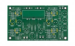
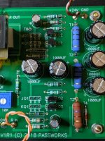
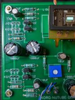
Q: Was this build from the diyAudio kit, with Q1, Q2, and R1 matched?
A: Yes, I bought the kit from diyaudio.com
Q: What is the value of the R1 resistors?
A: 150 ohm (brown, green, brown, gold)
Q: What is the voltage across each R1 (meter probe at each end of the resistor)?
A: right bottom - 66.9
right top - 67.9
left bottom - 65.8
left top - 65.8
Q: What is the voltage across V1?
A: I don't see any reference to V1 in the schematic or build guide. Please elaborate.
Q: What is the voltage across V2?
A: I don't see any reference to V2 in the schematic or build guide. Please elaborate.
Q: What is the voltage across V5?
A: I don't see any reference to V5 in the schematic or build guide. Please elaborate.
Q: What is the voltage across V6?
A: I don't see any reference to V6 in the schematic or build guide. Please elaborate.
Q: Did you measure the voltage at T5 and T6 and were they correct?
A: T5 - .63
T6 - .64
Q: Did you adjust the pot in each channel to try to get 10V at T7 and T8?
A: Adjusting the pot resulted in no change from 0
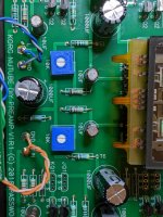
Q: What is the voltage across the 332k resistors?
A: The "top" 332k resisters on both sides are 33.1 on my meter (set to V 200k). The rest are -69.6, -72.3, -72.3, -72.3, -72.3, -70.3
Q: What is the voltage across V3?
A: I don't see any reference to V3 in the schematic or build guide. Please elaborate.
Q: What is the voltage across V4?
A: I don't see any reference to V4 in the schematic or build guide. Please elaborate.
And for good measure...
T1 - 23.8
T2 - 23.3
T3 - 22.7
T4 - 8.7
Attachments
-
 1.jpg398 KB · Views: 173
 -
 2.jpg454.5 KB · Views: 153
 -
 3.jpg426.2 KB · Views: 126
 -
 4.jpg427.2 KB · Views: 130
 -
 5.jpg433.5 KB · Views: 129
 -
 6.jpg290 KB · Views: 127
 -
 7.jpg424.9 KB · Views: 121
 -
 8.jpg386.1 KB · Views: 120
 -
 9.jpg370.4 KB · Views: 114
 -
 10.jpg561.6 KB · Views: 139
 -
 pot_spaghetti.jpg282.8 KB · Views: 108
 -
 power.jpg390.9 KB · Views: 108
 -
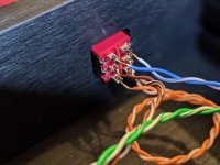
 selector.jpg395 KB · Views: 129
 -
 all.jpg531.9 KB · Views: 147
Your transistors are in the wrong positions. You should have populated JQ1 and JQ2, matching resistors and JQ2 transistors go together.
That'll do her. I do recall that section being less than sensical but I was tired and trying to drive on. Reading it now, it makes perfect sense. I suppose a picture is worth a thousand words. Thanks for the help guys.What bloqhed said. See attachment for J113 locations.
Re:V1 to V6: Those were the voltages at the resistors that I marked up on the attachment image of the pcb.
Hi Paul
Many questions...
Quote: I believe this is the primary post of yours that you are referring to although there are certainly other posts you made"
All of your questions have been addressed some years ago when I built the B1K. You found one post on one topic, but there are several posts on the caps alone, not mentioning other contributors around these posts!
May I kindly suggest you use the advanced search function of this forum? You could look at all my posts in this thread and also the ones that are next to it that triggered a discussion around similar topics then the one you raised.
Other than that...
1) Yep, you got the Fc choice right for the caps dimensionning. There is no reason for chosing the first 2 caps values other than that HP filter. The least possible capacitance was chosen not because it sounds better (that's debattable and I won't get into that one as completely marginal anyway in our case) but because if you follow the Fc rule we chose there is no main reason a bigger one will sound better, nor worst BTW. So indeed you could use bigger caps (hot debate on marginal effects if ever, some claim bigger is slightly better, some the opposite, both agree minor effect) but once you factor in size / form factor and costs you soon realise these can be an issue and you are far better off going for the smallest possible value not just soundwise.
Having said all that, I am convinced that if the cap follows the Fc rule we chose there is no reason a bigger one will sound better but as said I won't get into the cap's sound debate. You will also find some debates re sound vs max voltage rating, although possibly with more facts (construction) behind, but again won't get into that, thay are other threads for that.
2) Quote "I'm especially curious about that since there is a post somewhere by Papa saying 1uF would be the lowest values he would consider using", "I confess that I don't understand the underlying principles of all this thus by questions."
You may really want to use the search function and read all the posts.
3) Quote "On a completely different note, is inverting the phase at the DAC the same as inverting phase at the speakers by reversing the + - connections?"
That's another hot topic which has been also debated in length, not always an easy one. Please again use the search function. One of the reasons I post in such length in this forum is exactly to provide exhaustive answers one can refer to... years later. It costs time but then I don't have to do it again. Oh, another big reason is also to enable myself to refresh my memories on what I did on some projects years later, in order not to reinvent the wheel or myself GLOL!
Short answer to your question is: NO, it isn't the same.
Inverting the phase of the DAC AND biasing the B1K differently as I did it (in MY case around 13,5V instead of 9,5V) will though result in the same.
Have fun
Claude
Last edited:
Hi All, I plan to give the battery 18650 x 6 for the 24VDC directly to the main board, not sure it should be still via regulator is better? Or direct connect is well?
Hi guys - complete Noob to the forum here.
About to set out on my first ACA monos and B1 Triode Preamp build with my 12 y.o. daughter (and my first soldering in 20 years)
Is a Fluke 101 going to meet my needs in terms of resistor checking etc or should I stretch to a Fluke 17B+?
About to set out on my first ACA monos and B1 Triode Preamp build with my 12 y.o. daughter (and my first soldering in 20 years)
Is a Fluke 101 going to meet my needs in terms of resistor checking etc or should I stretch to a Fluke 17B+?
Hi Claude,
Thanks for those answers. As I noted in my first post, I have read hundreds of posts on here, including many dozens by you in many of which you tell people to use the search function. Let me say that I think you overestimate the utility of searching through nearly 7500 posts in this thread. I have already spent many hours reading the thread and I'm sure countless others have spent many hours looking for a few nuggets of your wisdom. Perhaps I missed the post where you wrap all this up into a tidy package. If that already exists I would suggest you simply copy its link, keep it someplace you can find it easily, and paste that link when somebody like me asks inane questions. If you haven't made that kind of concluding post doing so might save you time. If you do that, you should know that the kinds of people like me that ask inane questions don't know what the Fc rule means and searching on that isn't particularly enlightening.
I think the gist of what you are saying is that you felt that smaller capacitance ought to sound better within the limits of what the circuit required and size and costs were also important considerations. The values chosen were somewhat arbitrary but you, and most of the people that followed your work, feel the values you choose resulted in a worthwhile improvement in sound. And I and others should feel free to try other values and report back 🙂.
Thanks.
Paul
OK, understand... different apprcoach then, hope that works, as I don't have time to synthetise my own posts
Key words outside of my posts, I suggest you Google "RC high pass filter". Lot of small pages / quick easy reads for various levels. Fc is not a rule but the corner frequency. Look at the shape of the response curve and phase shift: important is not what happens at 5Hz (that figure is merely a resultant), but what such a filter still does at 20Hz / affects music if Fc is not chosen low enough. Arbitrary... well, the choice of Fc is, but based on facts.
Other than that, never said that smaller caps sound better. I said that bigger than required / calculated is unlikely to bring any real sonic benefits while of course as small as required enables easier fitting and is better for the wallet. But I wasn't cost driven - if that's the case, stick to what Papa recommended: excellent VFM!
Also, please note the sound improvement has NOTHING to do with the values I chose for my build. The values recommended by Papa are absolutely fine. They are very conservative, bigger than required at least for the two first ones, but that enables multiplying same references / kind of standardization. And is easy not to get confused etc. The sound improvement I perceive is solely due to the nature of the cap: good lytic vs good PPP, well noting most PPP are excellent anyway, so the quality of the cap and its tech if you prefer. That's the key here for the sound improvement, not the values chosen. So re playing with different values... increasing is likely to bring no benefit, while decreasing the cap values I took is likely to have detrimental effects (less bass response).
If you want to play, try different caps rather... flavours...
Good luck
Claude
Thank you Sir!It will be fine. No expensive meters needed.

I'm thinking of mating a B1 with an NCore module in a very nice wine box (hinged top door). I think it would make a very good sounding integrated amp.
BUT... I'm concerned with the post about a B1K blowing up an NCore module.
Should I provide for separate ON/OFF switches for the B1 and NCore module? Some kind of a complex, staggered power up schema like in a B1B?
Note, I have a B1 and a B1K already, and the B1K does put out a pop... so normally, I power it up before I power up the amps. I don't recall the B1 doing so.
Hi, I have both (not in the same box) & have had no problems, original unit had quite a big start up pop. My 2nd unit, which I paired with a Muses V/C from Audio Academy. This V/C recommends you put a DC blocking capacitor before the Muses V/C, which I did. Still a little pop, but much quieter.
Cheers
Cheers
62 week lead time?Hi, I have both (not in the same box) & have had no problems, original unit had quite a big start up pop. My 2nd unit, which I paired with a Muses V/C from Audio Academy. This V/C recommends you put a DC blocking capacitor before the Muses V/C, which I did. Still a little pop, but much quieter.
Cheers
https://www.mouser.com/ProductDetail/Nisshinbo/MUSES72320V-TE2?qs=yQ3iditm8N4Rmh8eV8%2BOSA==
I've got Purifi Eval1 and B1K in one box with one on/off switch. Works like a charm. But the Hypex power module has got an inbuilt delay. I did use a fixed voltage divider on the B1K outputs.I'm thinking of mating a B1 with an NCore module in a very nice wine box (hinged top door). I think it would make a very good sounding integrated amp.
BUT... I'm concerned with the post about a B1K blowing up an NCore module.
Should I provide for separate ON/OFF switches for the B1 and NCore module? Some kind of a complex, staggered power up schema like in a B1B?
Note, I have a B1 and a B1K already, and the B1K does put out a pop... so normally, I power it up before I power up the amps. I don't recall the B1 doing so.
Interesting..
(1) You removed the female banana speaker terminals and added new five way binding posts?
(2) What kind of power supply did you use? Is that the NCore 1200w SMPS?
(3) How do you connect the output of the B1K to the input of the Purify module? Is it an external jumper with a single ended to balanced adaptor?
Hi, here is the link for the Academy Audio Muses board
https://www.academyaudio.com/evc
It is now reduced from $99 to $69.
Cheers
https://www.academyaudio.com/evc
It is now reduced from $99 to $69.
Cheers
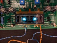
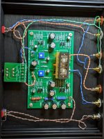
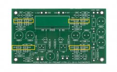
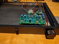
Enjoying my first unit for over a year, decided to build a second one of these. First one was a full kit. For the new one I bought the Nutube and board from diystore. Sourced wall wart, resistors and caps from Mouser, everything else was in the parts bin including volume knob, pot, wires, case and connectors. Built as a single channel buffer but left room for another set of inputs is needed. Using as a buffer, volume at 12 oclock is unity gain.
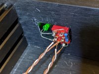
Added a 12V circuit for relays and comparators. When pulgged in, 12V is always powered and the red LED indicates StandBy. The on switch sends 24V to the main board, and also starts a 16 second timer to allow thumps to clear before the output relays are enabled. Both LEDS are on until the relays enable at which point the red StandBy lamp goes out. Unit can be unpowered (unplugged) and the input will pass thru to the output.
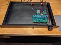
Built it in a cheap 1U rack. Used one side in case I wanted to do something else in the future. Probably will upgrade the PS and add IEC.
Added a 12V circuit for relays and comparators. When pulgged in, 12V is always powered and the red LED indicates StandBy. The on switch sends 24V to the main board, and also starts a 16 second timer to allow thumps to clear before the output relays are enabled. Both LEDS are on until the relays enable at which point the red StandBy lamp goes out. Unit can be unpowered (unplugged) and the input will pass thru to the output.
Built it in a cheap 1U rack. Used one side in case I wanted to do something else in the future. Probably will upgrade the PS and add IEC.
Attachments
- Home
- Amplifiers
- Pass Labs
- B1 with Korg Triode