Thanks JP, as I thought, I have used the typical spray bottle clear coat stuff, checked one on my shelf and was acrylic, I have used it mainly on some computer parts like HD PCB, graphics card etc due to excess dust collecting from all the spinning fans and the parts are still working after years of use, those BGA chips get a lot of dirt underneath so I do spray a bit extra around these components to seal up, but at the same time I am still a bit worried over the potential thermal expansion issues might cause some problem, it's a bit of DIY guess work here, but then I never turn off my PC, just from my own experience PC's continuously powered on year in year out seems to hold better.
In my opinion...the problem of thermal expansion is not a problem...but heat exchange by natural convection...yes.
I don't see the point of varnishing a pcb used indoors...
Except maybe in a cave.? 🙄
I don't see the point of varnishing a pcb used indoors...
Except maybe in a cave.? 🙄
But not for resistors, caps, op-amps and transistors... or?....
https://trollfactory.de/anwendungen...-laminierharz-bis-10mm-inkl.-einweghandschuhe
It works very good and indeed takes 2 days to cure. As a result it does not heat up. Of course transformers that are molded need to be overdimensioned and then derated. Toroids become almost silent when molded. Electronics can be molded too but once molded repair is out of the question.
//
mmmm, I count resistors, caps, op-amps and transistors as electronics 🙂 Anyone is entitled to opinions but I coat every SMD populated PCB and have good experiences protecting conductors against dirt/moist etc. Let's say the positive outweighs the negative (if any). Surfaces of parts that develop heat of course are wiped with cotton buds and some isopropyl alcohol. Since getting rid of excessive heat (by design!) and designing green is my hobby I get away with things. No class A, resistors dissipating a few Watts etc.
Molding vibrating stuff like transformers also works out great provided one overdimensions/derates the transformer. Old tube transformers with sometimes brittle wire insulation is then also solved.
Molding vibrating stuff like transformers also works out great provided one overdimensions/derates the transformer. Old tube transformers with sometimes brittle wire insulation is then also solved.
Last edited:
Does anyone have any experience with this little fella'? https://www.aliexpress.com/item/400...;265.52;-1;-1@salePrice;SEK;search-mainSearch
I would be cautious about ordering anything right now. My order is stuck in Shenzhen...
https://www.nytimes.com/live/2022/03/13/world/covid-19-mandates-cases-vaccine
https://www.nytimes.com/live/2022/03/13/world/covid-19-mandates-cases-vaccine
I received my amp yesterday. Guess I was being a bit of an alarmist with my previous post, but we live in crazy times. 18 days from order to delivery.
Mine is the newer board without the pads for the ferrite beads, but that's easily remedied with an x-acto knife.
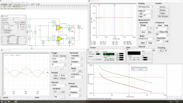
It has genuine WIMA coupling caps (raised lettering on the top), but they're only 1uF and not only pointless, but detrimental. I sim'd the input circuit in TINA, and with the 1uF caps the response is down over 5dB at 20Hz. I immediately noticed the lack of bass when I hooked it up for initial testing.
I've decided to just replace the TL072 with OPA1642 and leave the rest of the input circuit alone other than replace/bypass the coupling caps. It sims way better than any OPA1632 circuit. The sim results with OPA1642 are so good that I almost don't believe them. With a 1Vrms differential signal the results are 134.4dB SNR, 5.12nV/√Hz output noise, 165nV total noise, and 0.0086% THD.
The output of the op-amps is asymmetrical, but it sums nicely to 1.63Vrms with 1Vrms input. I won't pretend to understand how that works.
Still waiting on some parts for the output filter.
Mine is the newer board without the pads for the ferrite beads, but that's easily remedied with an x-acto knife.
It has genuine WIMA coupling caps (raised lettering on the top), but they're only 1uF and not only pointless, but detrimental. I sim'd the input circuit in TINA, and with the 1uF caps the response is down over 5dB at 20Hz. I immediately noticed the lack of bass when I hooked it up for initial testing.
I've decided to just replace the TL072 with OPA1642 and leave the rest of the input circuit alone other than replace/bypass the coupling caps. It sims way better than any OPA1632 circuit. The sim results with OPA1642 are so good that I almost don't believe them. With a 1Vrms differential signal the results are 134.4dB SNR, 5.12nV/√Hz output noise, 165nV total noise, and 0.0086% THD.
The output of the op-amps is asymmetrical, but it sums nicely to 1.63Vrms with 1Vrms input. I won't pretend to understand how that works.
Still waiting on some parts for the output filter.
Attachments
Mine is in use since I modded it and it sounds decent. Stock I also noticed lack of bass even though the film caps were 2.2 uF.
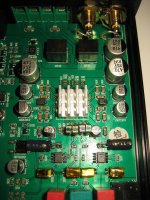
Finished the input mods. The low end response is incredible now. Used 40pcs ECPU1C105MA5.
When testing the amp with the top cover off, I noticed there's some fairly audible switching noise even a idle. Not sure if it was like that before the mods; didn't test it with the cover off initially.
One of the inductors on mine is marked 150 (15uH). When I model the filter, there's a peak of over 30dB around 1.8MHz. I wonder if the filter is causing instability. Well, that's the next mod once my inductors arrive.
Attachments
Well done with the caps!! I take you solder one after one at one side with the wire?! Then solder the other side?
I wish I had thought of doing it like that.
I wish I had thought of doing it like that.
I've modeled some LC output filters for class D amps too. It turns out they peak, without a 4 - 8 Ohm resistor load. Which I take that to be the speaker. So who knows what the LC is actually doing with a real speaker load - guess it's close enough.One of the inductors on mine is marked 150 (15uH). When I model the filter, there's a peak of over 30dB around 1.8MHz. I wonder if the filter is causing instability. Well, that's the next mod once my inductors arrive.
In the TI paper on class D filters, they warn to not let the filter peak, with stated consequences to sound quality and operational reliability (nuisance shutdowns).
I solder "stacks" of the caps and then solder the wires on after. I have a pair of small cross lock tweezers I use to hold the stacks together. They're fairly tolerant to heat as long as you don't linger with the iron too long. I haven't melted one yet or measured any capacitance change after.
Last edited:
The problem is that the filter used is completely outside of anything recommended in the application notes. A 30dB peak at any frequency unacceptable, but especially at RF. It's like the designer just threw random parts at the board.I've modeled some LC output filters for class D amps too. It turns out they peak, without a 4 - 8 Ohm resistor load. Which I take that to be the speaker. So who knows what the LC is actually doing with a real speaker load - guess it's close enough.
In the TI paper on class D filters, they warn to not let the filter peak, with stated consequences to sound quality and operational reliability (nuisance shutdowns).
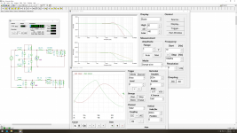
Ok, so I was doing something wrong when I simulated the original output filter earlier. Now that I think I'm doing it correctly, the peak isn't there. It still isn't a great filter.
Attached is pic of my proposed filter that's mainly influenced by parts I have on hand, while trying to somewhat balance response with 4-8Ω loads, compared to the original filter. A simulated reactive load is used to get more realistic results (I think).
Attached is pic of my proposed filter that's mainly influenced by parts I have on hand, while trying to somewhat balance response with 4-8Ω loads, compared to the original filter. A simulated reactive load is used to get more realistic results (I think).
Attachments
Filter mod complete. I taped two SER1052-572ML together for each channel and they just happened to fit the footprint perfectly.
My ears are more pewter than golden, so I'd be lying if I said there was any significant difference in the sound without being able to A/B. Maybe a little less shrill up top, but it could just be my imagination. At least I can use it knowing it isn't an EMI nightmare with my 6ft long speaker cables.
Wish I knew my way around I2C programming so I could set the power profile.
Attachments

OK, so that endeavor was mostly pointless. I bought an I2CMini board and took a crash coarse in I2C which nearly imploded my 90IQ brain.
After barely managing to get the leads from the I2CMini soldered to the IC, I was successfully able to to read and write data. I had assumed the settings would stick with a power cycle, but that's not the case. So I guess you need some type of MCU to write the settings at every boot. Bummer.
My goal was to run it in Power Mode A at all times. Oh well, at least I learned a little about I2C.
EDIT: I should also mention that means this amp runs in Power Mode Profile 0 since that's the default, which isn't the best one for THD+N.
Last edited:
I have the same issue with my Zoudio amp. I'd like to run it in a different mode and there's even a programmer and a micro to load the values at every power on, but a change to that setting wasnt made available at a user level. The TAS chip offers the functionality, the OEM assumes the majority of their customers want "best battery life" and made that permanent. *** the battery; give me best THD+N. Make the battery users change it if they want to squeak another 5-10 minutes out of their charge...OK, so that endeavor was mostly pointless. I bought an I2CMini board and took a crash coarse in I2C which nearly imploded my 90IQ brain.
After barely managing to get the leads from the I2CMini soldered to the IC, I was successfully able to to read and write data. I had assumed the settings would stick with a power cycle, but that's not the case. So I guess you need some type of MCU to write the settings at every boot. Bummer.
My goal was to run it in Power Mode A at all times. Oh well, at least I learned a little about I2C.
EDIT: I should also mention that means this amp runs in Power Mode Profile 0 since that's the default, which isn't the best one for THD+N.
It just seems silly to me that if the application requires even the smallest change to the default parameters, like simply using a different power mode, that it requires implementing an MCU in the design.
I'm sure it can be done with something as simple as an Attiny85 or similar, but I have zero programming knowledge.
I'm sure it can be done with something as simple as an Attiny85 or similar, but I have zero programming knowledge.
Last edited:
Welcome to the world...of today's high tech paradigm. The time will come when every chip is this way. I remember the glory days when you could choose among internal parameter settings simply with a particular resistor value to ground on a pin.It just seems silly to me
Ah it is not the worst either. How does the amplifier with the modifications compare with other amplifiers you have?I should also mention that means this amp runs in Power Mode Profile 0 since that's the default, which isn't the best one for THD+N.
Mine has been connected and stayed connected since then as it has a good sound character. Good sign as most stuff is disconnected after testing/listening.
- Home
- Amplifiers
- Class D
- Infineon MA12070 Class D