Add a driven element to simulate a woofer and you will complete the picture 🙂You will have the opportunity to examine all of this for yourself soon.
The roundovers (or not) on the back and width depth ratios affect the woofer pattern much more than they do a waveguides.
It's possible to place the waveguide anywhere on a front baffle of any size but what you suggest would require quadrupling the number of BEM elements and considerably longer calculation time - something I won't try at the moment (up to now everything was in 1/4 symmetry). I leave that as an excercise for others...Can you extend the bottom of the enclosure by 1x its length, to show a waveguide position in a two way enclosure, and make a vertical up and vertical down polar plot, or is this still too early with current scripting means?
Last edited:
A woofer can be simulated separately by means of the Source Definition Script. Any diaphragm profile can be defined that way.Add a driven element to simulate a woofer and you will complete the picture 🙂

Hmm, higher DI < 1kHz with deeper enclosure, interesting. Perhaps it is just sound going around the enclosure, path length around the enclosure elongates total 11cm from the slim to middle, then 17cm from middle to deepest, and the "boost" seems to move from ~1.2kHz to ~1kHz and down to ~800Hz. Diffence is not big though, maybe 1-2db difference total on 800Hz between on axis and back for example. Made gif from the responses.
Attachments
Doesn’t take much work to be honest. Fusion 360 CAM is great but I do have issues with surface finish using scallop / change of tool path direction. Maybe some backlash in the old ball screws! Here’s the almost finished tool. A little sanding and polishing to go.Wow, I wish I had those capabilities and tooling. Wonderful job, unrivaled.
Attachments
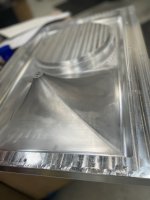
is this a mold for fiberglass/carbon etc?Doesn’t take much work to be honest. Fusion 360 CAM is great but I do have issues with surface finish using scallop / change of tool path direction. Maybe some backlash in the old ball screws! Here’s the almost finished tool. A little sanding and polishing to go.
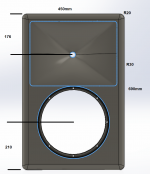
So this is a rectangular waveguide in a box (W x H x D = 254 x 206 x 200 mm):

Horizontal, vertical, diagonal polars:


Horizontal, vertical, diagonal polars:
The same WG in a box and in an infinite baffle (horizontal polars, 0-90 / 5deg):


Looking at where you are going with this, I think the next logical thing to investigate is cabinet width...for example my cabinets are 32" wide.
Because a finite baffle width and depth diffracts creating directivity, and confining the angle increases output.Why does the box show more output and higher directivity below 1 khz than the IB?
^^ I guess it is the diffraction hump, seen on any diffraction sim just above bafflestep, just below 25cm wavelenght in this case, about 1.3khz
The best baffle for a waveguide is the one with least excess flat area either side. A decent roundover or chamfer right next to the guide works like a bigger termination.Looking at where you are going with this, I think the next logical thing to investigate is cabinet width...for example my cabinets are 32" wide.
Look at the infinite baffle example youd that that the closer you moved towards it...the better things get.The best baffle for a waveguide is the one with least excess flat area either side. A decent roundover or chamfer right next to the guide works like a bigger termination.
Just out of curiosity -


Last edited:
- Home
- Loudspeakers
- Multi-Way
- Acoustic Horn Design – The Easy Way (Ath4)