Yes. I would say any Zout below 20K for both outputs would qualify as voltage drive for even large ESLs.The Zout of my prototype DD amp is about 4k at each output. I think that qualifies as voltage drive in this context, yes?
I appreciate your clarifying comments for some of the details I glossed over.Thanks Bolserst - nice plot!
To be clear:
...
I was describing the linearity of the factor or parameter that would be loading the diaphragm when it is playing music.Are you using "linearity" to describe the traces or the linearity of that factor when the membrane is playing music?
I don’t recall saying this; do you happen to recall the context? Other than in the top octave, the mechanical impedance from the weight of the diaphragm is nowhere near a match to the radiation resistance. Whatever the magic of ESL’s sound, impedance match between the air and the diaphragm is not the explanation.Especially as you say, the radiation resistance is not a bad match for the weight of the membrane. Which is the magic of ESLs.
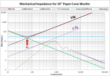
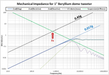
I’m not sure if you have read the Rice/Kellogg AIEE paper on their testing and developmental work on a range of transducer types(including ESLs) leading to recommendation for the moving coil loudspeaker. One of the key features they pointed to was the fact that is was mass controlled over nearly its entire useful range. For comparison with the previously posted ESL mechanical impedance plot, here are plots for a typical 10” woofer and 1” tweeter where you can see this feature of mass control is still present today.If the same analysis were done before Rice and Kellogg made their driver, everybody would have said shaking cardboard to make sound would be a waste of time.
Attachments
I agree that damping material needs to be kept from moving. However even when it is, I have experiences some felts, foams, and metal mesh that introduced unexpectedly high 3rd harmonic even when glued to perforated plates to ensure they were stationary. Another issue that can arise when damping mesh isn’t stretched tightly, is that is can have a self resonance like a diaphragm. The effective damping resistance drops nearly to zero in the range around this resonance.It's actually the damping material moving that creates distortion. It needs to be stretched quite tight. Silk is favoured by mike designers cos it is very consistent but I've used tightly stretched plain 'cloth' to damp EML speakers with success.
Some impedance tube measurements were posted for acoustic mesh held with different tensions here:
https://www.diyaudio.com/community/...ots-for-resonance-control.152979/post-5978781
I'm not sure felts or foams are appropriate for 'flow resistance' damping. OK when absorption is required.I agree that damping material needs to be kept from moving. However even when it is, I have experiences some felts, foams, and metal mesh that introduced unexpectedly high 3rd harmonic even when glued to perforated plates to ensure they were stationary.
I've never used metal mesh for this type of work. Fine weave cloth glued to a a perforated stator is probably what's required. Anyone remember how ESL 63 was done?
This happens with the walls of box speakers too. We did a lot of work on 'stiff' boxes using fancy materials and showed loadsa SCAnned Laser Plots in our marketing guff. But in truth, 'stiff' boxes have just as much sound coming through the walls as cheapo MDF and more traditional boxes .. including near transparency at 'resonance'. The real advantage is that the 'leakage' is sounds 'nicer' 🙂.Another issue that can arise when damping mesh isn’t stretched tightly, is that it can have a self resonance like a diaphragm. The effective damping resistance drops nearly to zero in the range around this resonance.
Nothing other than what I can see from searching the web....Some time ago you mentioned a British company working on a pulsating esl sphere, striving to approach a real point source.
Any news on their progress as far as you know ?
Looks like they have quite a few reviews now(none with measurements that I see though) and 2 dealers added.
https://www.frontro.co.uk/
For those that weren't following Hans Polak's work on modeling the ESL63, here are few links to posts discussing/comparing the FrontRo ESL with the ESL63.
Includes descriptions, polar plots, and links to papers and patents.
Post#225
Post#236
Post#258
Post#261
Post#262
If the panel have zero resistance (not in realistic), then the charges are shuttled from one stator to the other thru the transformer secondary or other conductive path indefinitely (AC) and the diaphragm will keep oscillate or vibrate back and forth indefinitely?The 2nd term in the Force formula has the transduction coefficient ∝ built into it. Damping isn’t part of the force equation; rather it results from the electrical and mechanical domains communicating with each other thru the transducer motor. An applied voltage results in force on the diaphragm which in turn results in the diaphragm attaining a velocity which produces a motional current. If there is some resistance included in the electrical circuit, the voltage drop across the resistance due to this current counteracts some of the applied voltage resulting in reduction of the force and velocity (ie damping).
With ESL, assume Re is very low, thus Rm is very low. If it's playing music signal, and suddenly the music signal ceases (Vsig=0). The diaphragm doesn't stop immediately, so it continues to be in motion. Since it has velocity, it will produce motional currents, then the voltage drop isn't much, and therefore produces force on the diaphragm. Is this force opposite to the velocity (opposing the it's motion), causing it the 'brake', or....?Comparing transduction coefficients, BL = 10 is pretty typical for an EML, and ∝ = 0.002 for an ESL.
The other difference is that the EML motor behaves like a gyrator and an ESL motor like a transformer.
View attachment 1030465 View attachment 1030466
One consequence of this difference is that adding resistance in the electrical domain has opposite effects in the mechanical domain. For EMLs, minimizing electrical resistance provides the most damping of the mechanical system. For ESLs, resistance must be added to the electric circuit to damp the mechanical system. As mentioned previously, it isn’t very effective. As an example, here is a trend for an 400pF ESL panel with increasing resistance added in the electric circuit.
View attachment 1030467
Even with 1Meg of resistance very little increase in damping is seen, and the power response is rolling off at high frequencies due to the first order LP filter formed between the series resistance and the panel capacitance. Note that as you continue to increase resistance the Q actually starts to go back up and the resonance increases to the unpolarized resonance frequency. This is because the resistance is >> impedance of the panel capacitance so you are in effect driving the panel with a current source. The negative compliance -Ce is then cancelled out by the panel capacitance Ce as explained in the Baxandall ESL chapter. It is all rather academic since so much sensitivity is lost with high series resistance that it isn’t practical anyways. If interested, experimental results for this behavior were posted here:
https://www.diyaudio.com/community/threads/current-vs-voltage-drive-esl.175918/post-2366501
With EML, the force direction is opposite to the diaphragm motion, thus it 'brakes' the movement
Don't forget in ELS, there is always a mechanical resistance due to the air load. Also it is the air 'velocity' which to vibrating the diaphragm so when the sound stops, the vibration stops too. The diaphragm 'resonance' Q may be too high for flat response which is where additional mechanical/acoustic damping via stretched cloth may be requiredIf the panel have zero resistance (not in realistic), then the charges are shuttled from one stator to the other thru the transformer secondary or other conductive path indefinitely (AC) and the diaphragm will keep oscillate or vibrate back and forth indefinitely?
Yes. It's the same as with EML except it's the 'dual'. If there is a large electrical source resistance, the ESL velocity current will generate a voltage. The resultant voltage gradient acts on the charge and opposes its motion.Since it has velocity, it will produce motional currents, then the voltage drop isn't much, and therefore produces force on the diaphragm. Is this force opposite to the velocity (opposing the it's motion), causing it the 'brake', or....?
With EML, cone velocity generates a voltage. This voltage across the electrical coil resistance results in a current which generates a force opposing the velocity.
These give rise to the 2 eqns. for Electrical Damping. One I showed for EML and the other that bolserst showed for ESL
Nothing other than what I can see from searching the web.
Looks like they have quite a few reviews now(none with measurements that I see though) and 2 dealers added.
https://www.frontro.co.uk/
For those that weren't following Hans Polak's work on modeling the ESL63, here are few links to posts discussing/comparing the FrontRo ESL with the ESL63.
Includes descriptions, polar plots, and links to papers and patents.
Post#225
Post#236
Post#258
Post#261
Post#262
Similar can be done with small wide band drivers and CBT arrangement from Don Keele.
The distortion of EML and its causes have been explained in details by Klippel. On the subject of the ESL distortion (THD): As low as it is, but due to the fact that it's not an electret, but a finite high resistance diaphragm, it can cause some 3rd harmonic distortion. It's explained in the pages I've attached. Have anyone calculated or simulated this minimum theoretical limit of this distortion (Eq 3.73) using realistic capacitance and resistor (Ro) values that is being use by most ESL?
Attachments
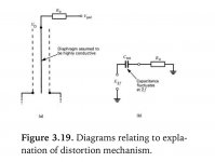
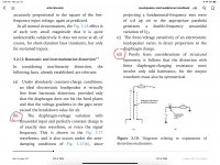
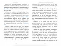
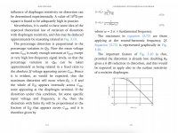
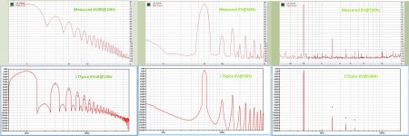
Not sure whether this answers your question, but I have simulated AND measured distortion of an ESL63 at resp 10Hz, 50Hz and 500Hz with a 6V input signal.The distortion of EML and its causes have been explained in details by Klippel. On the subject of the ESL distortion (THD): As low as it is, but due to the fact that it's not an electret, but a finite high resistance diaphragm, it can cause some 3rd harmonic distortion. It's explained in the pages I've attached. Have anyone calculated or simulated this minimum theoretical limit of this distortion (Eq 3.73) using realistic capacitance and resistor (Ro) values that is being use by most ESL?
In the first image, the top row shows the measured results versus the bottom row the simulated outcome.
With blue dots the measured harmonics are shown in the simulated graphs.
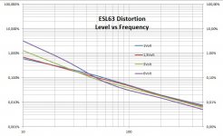
Second image shows measured THD for various input voltages up to 500Hz.
IMO EML´s can only dream of this sort of distortion.
Hans
Attachments
According to Stereophile, the ESL63 produces 86dB at 2.83V at 1m distance.Thank you Hans Polak, this is very helpful. 6V input is approximately how manhy dB?
So I would say, with 6V input, 6.5 dB extra.
Hans
Do you have the measurements and simulation for above 500Hz?Not sure whether this answers your question, but I have simulated AND measured distortion of an ESL63 at resp 10Hz, 50Hz and 500Hz with a 6V input signal.
In the first image, the top row shows the measured results versus the bottom row the simulated outcome.
With blue dots the measured harmonics are shown in the simulated graphs.
Second image shows measured THD for various input voltages up to 500Hz.
IMO EML´s can only dream of this sort of distortion.
Hans
This is what a Danish test measured, second and third harmonic up to 20Khz with 3V input.Do you have the measurements and simulation for above 500Hz?
Hans
Attachments

Comparing these Danish graphs with my measurements in #273, my impression is that 2H and 3H are interchanged.This is what a Danish test measured, second and third harmonic up to 20Khz with 3V input.
Hans
Hans
- Home
- Loudspeakers
- Planars & Exotics
- Electrostats vs conventional drivers