Hi Stef,
excuse my excitement, but I explained this effect in detail a few weeks ago and also published the simulations with R32 and the resulting DC offset.
So: there is a current across the + rail to input ground via R6. This current produces a voltage drop at R32. The input ground is the reference for the OPA via C2 and for the other stages R6. So the output signal is oriented to the voltage level of the input GND, while you measure the DC offset against the output GND.
In this course another explanation:
If C1 is connected to Input GND, the amplifier plays airy (this is high frequency distortion), if C1 is connected to Output GND, the amplifier plays the treble more precisely. I have visualised this effect on the simulation and practically heard it acoustically in direct comparison.
Regards Tim
One more thing:
R32 has a very significant effect on very quiet sounds: since the signals are offset by a voltage difference from the 0-axis of the output stage, only the plus output stage operates and there is no change above 0. This is important because when the Mosfet is switched on, capacitance is a significant disturbance. This switching on does not work with particularly small signals, so those must be removed from the 0-axis.
The optimisation with the simulation of the circuit must therefore be done in such a way that output signals of +- 100mV are generated, so with 36mV DC offset this is +136 / -64mV. This shows very precisely how the Mosfet is switched on and off at a lower level. These transitions do not look nice with a high-frequency square wave signal. This is not a deficit of the amplifier, but a worst case scenario. However, this worst case scenario is necessary to get an idea of how this amplifier works.
And I would like to add: it works especially wonderfully.
Hi Tim,
I'm not sure I understand all of this. From a practical point of view, is it useful to lower the value of R32 resistor?
Stef.
I'm not sure I understand all of this. From a practical point of view, is it useful to lower the value of R32 resistor?
Stef.
No the reduction of R32 is not helpful.
The current through R6 is essentially defined by R3. I have reduced R3 to 100 ohms and accordingly obtained a DC offset of approx. 54 mV. This means: R3 should be large, but then this stage does not work properly. Therefore, R3 with 150 Ohm is ideal.
R32 should not be too small, because with the reduction, the oscillation probability increases significantly, with a simultaneous reduction of ideal small signal behaviour.
This circuit also eliminates power supply hum, which I found out during my experiments with a GND resistor network. Therefore, the value of R32 is very ideal.
For sound considerations only, I can imagine a value of 12 ohms for R32. Below 10 ohms, in any case, there is no advantageous result.
Normally one would expect a DC offset of an amplifier to cause a deformation of the output signal. Therefore, minimising the DC offset is an objective. With the Q17, the DC offset makes the output signal more precise in the very low level range, i.e. with electrical signals smaller than the DC offset.
From this it follows:
From what is written here, it follows that when the DC offset is minimised below the threshold voltage of the capacitors of the output transistors, the Q17 must start oscillating because it can no longer find a 0-point. Therefore, when you connected R6 to output GND, the Q17 broke off. Sorry, I was not aware of this in such clarity at that time.
From what is written here, it follows that when the DC offset is minimised below the threshold voltage of the capacitors of the output transistors, the Q17 must start oscillating because it can no longer find a 0-point. Therefore, when you connected R6 to output GND, the Q17 broke off. Sorry, I was not aware of this in such clarity at that time.
Ok thanks Tim. It's much more understandable.
With the new PCB, the "noise" seems below compared to the first version. It's probably due to the more optimized PCB and the LPF at input. I also received some OP1611 to compare with the OPA1641.
I wasn't going to be able to do 50V PSU tests right away because I'm missing parts to finish the 50V test power supply that I'm building. I found a large 2x34VAC transformer in one of my closets. I don't want to use my currently finished and working Q17 amp for testing purpose.
Later, I plan to disassemble the components of my two Q17 1.0 boards and reassemble everything on the new PCBs.
Regards,
Stef.
ps: A few weeks ago, I tried with the Q17-P2 PCB to connect R6 to output GND -> smoke. 😉
Attachments
Hi All,
Is there any tested and stable design of Q17 with multiple output mosfet pairs( for higher watts), kindly point me to the gerbers if available.
Regards,
Suman
Is there any tested and stable design of Q17 with multiple output mosfet pairs( for higher watts), kindly point me to the gerbers if available.
Regards,
Suman
A two pair pcb, including gerbers, is available to download from the very first post of this thread.
I'm currently using a two pair Q17 on a previous version of the pcb, so the one I have posted have some things improved.
To achieve higher power, you need higher power supply voltage. The limiting factor are output Fairchild devices that can be run at max Vds=150V. This translate in a absolute maximum +/-75Vdc power supply which I do not recommend.
To be on the safe side, +/-65V would be my recommendation.
At +/-65V maximum theoretical output power would be around 250W/8ohm. In practice this will be ~200W/8ohm.
This power can be achieved with only one pair of Fairchild as well. These transistors have enough transconductance to push high current in low impedance loads.
Having two pair will allow to drive even lower impedance speakers, like ESL, or almost any high-end speaker.
Regards,
Tibi
Hi all
Thank you stephan for your suggestion to try Digikey for opa1641. they had several in stock indeed. But I did not order them because of the High transportation cost (18euros) for only two cheap chips. I am a kind of a cheap goat!
What I did, I managed by bending the feet of the tiny flees ,I orderd by mistake, and believe it or not, I could let them make contact with the tracks of the bigger size chip on Tibi's board.
And they work!
After a lot of hours continuous listening, I must confess that I am tres impressé, What a beast. Very refined mids and highs and beautiful base! At any listening level!
And man, what dynamics! The negative side of things is, that even very small ticks one of my dacs give ,when switchen to a different sample family,
it sounds like a gun-shot! Painful for both ears and speakers. Remedy is using another dac!
I cannot stop listening, especially in the small hours when it is quiet around the house!
Big thanks to Tibi for this wonderfull thing.
One question before closing:
I use Tibi's Psu includig the self built tht Saligny. Fed by a 36volt 300vA ring-traffo, making round 52volt DC.
At switching on the unit, it blows about every fuse I put in it. I started with 2,5amps manually increasing the house power from zero to max (230 Volt).
No problems here.
When switching the power on in one instant to 230Volts, about any fuse blows! I went as far as a 6,3 amps fuse with reasonable succes, but one of three times, even one or two fuses still do blow.
I could go to eight or ten amps, but am afraid thats not a very safe action.
The big transformer has a very big inrush when switching on. Even the lights in the house dimm a litlle.
What is the advise to handle this more smoothly.?
Regards,
Ed

@ed linssen try a simple CL60 thermistor as soft start in the transformer primary line in series. Other option is to use a good quality soft start module. I am using a simple CL60 even though my rails are only +/-33vdc and no fuse blows or any kind of thump because of inrush current etc.,
Thanks
Thanks
Hello Ed,
I found a softstart and a speaker protection circuit here in the forum, which I also laid out as a PCB a few months ago and uploaded here. Since I always have space problems in my cases, I have these circuits now also individually.
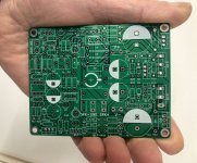
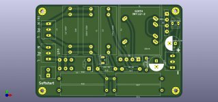
I'll upload you the Gerber for the soft start here, that's quite useful and has often benefited me in my experiments that only the fuse blew but the rest stayed intact.
There is still room on the PCB for a transformer Gerth 3,6 or 4,8VA, as well as rectifier and current smoothing, for example for a radio potentiometer for volume control.
Regards Tim
I found a softstart and a speaker protection circuit here in the forum, which I also laid out as a PCB a few months ago and uploaded here. Since I always have space problems in my cases, I have these circuits now also individually.
I'll upload you the Gerber for the soft start here, that's quite useful and has often benefited me in my experiments that only the fuse blew but the rest stayed intact.
There is still room on the PCB for a transformer Gerth 3,6 or 4,8VA, as well as rectifier and current smoothing, for example for a radio potentiometer for volume control.
Regards Tim
Attachments
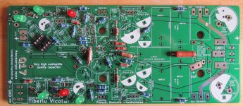
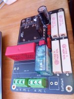
The assembly is not quite ideally labeled, for me it is sufficient.
Here is another picture, on it 470uF MKP4/630V are missing.
The relay is pretty standard, here is the finder: 40.61.9.024.0000.
The rectifier is also quite cheap: GBU4K
Here is another picture, on it 470uF MKP4/630V are missing.
The relay is pretty standard, here is the finder: 40.61.9.024.0000.
The rectifier is also quite cheap: GBU4K
Attachments
Thank you, Manniraj/Tim for your solutions! I am busy finding out what the simplist working way will be. I am busy now with both big resisters and ntc's with a two position switch, so I can cancel the influence of resistors etc. after being switched on.
Let you know if it is succesful,
regards, Ed.
Let you know if it is succesful,
regards, Ed.
Looking very good Tibi, next set of changes if you are doing please include the dip socket pads for the opamp so that we can do opamp rolling like the mini version of Tim. Becomes life easier as just need to solder the smd opamps on the dip socket boards and use on your amp boards.
Thanks
Thanks
- Home
- Amplifiers
- Solid State
- Q17 - an audiophile approach to perfect sound