Hi Marcel
Can you give my a hint with exporting the surface to Fusion360?
The .STL file looks fine. I can also import the ESP shape into fusion without any problems.


I have copied the code from the .pdf file, but I am not certain about the parameters:
In this configuration I get 32 separate .csv files with 33x3 values and an empty one, if I set SeparateFiles = 1.
When I set it SeparateFiles = 0 then I get one big file with +900 lines, where it seems like the last section is incomplete.
If I use the ath4_CurvesImport script in Fusion360 on the large file, then I get the profiles, or at least most of them:

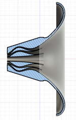
But, when I try to use ath4_SurfaceImport on the same file it doesn't work.
So what should my ProfileRange and SliceRange be?
Should ProfileRange be smaller than Mesh.AngularSegments?
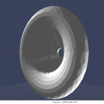
Looks like it works with importing the surface, but I'm not sure if I have exported the whole thing. I have set SliceRange = MeshLengthSegments - 1, I guess there can't be overlap in the mesh

I'll keep on trying 🙂
-Daniel
EDIT:
Great succes

Can you give my a hint with exporting the surface to Fusion360?
The .STL file looks fine. I can also import the ESP shape into fusion without any problems.
I have copied the code from the .pdf file, but I am not certain about the parameters:
Code:
Rollback = 1
Rollback.StartAt = 0.4
Rollback.Angle = 180 ; [deg]
Rollback.Exp = 1.5
Mesh.AngularSegments = 32
Mesh.LengthSegments = 60
Mesh.SubdomainSlices =
Mesh.WallThickness = 4 ; [mm]
Mesh.ZMapPoints = 0.5,0.4,0.5,0.98
ABEC.SimType = 2
ABEC.SimProfile = 0
ABEC.f1 = 200 ; [Hz]
ABEC.f2 = 20000 ; [Hz]
ABEC.NumFrequencies = 100
ABEC.MeshFrequency = 42000 ; [Hz]
ABEC.Polars:SPL = {
 MapAngleRange = 0,180,37
}


GridExport: = {
 ProfileRange = 0,32
 SliceRange = 0,32
 ExportProfiles = 1; 0|1
 ExportSlices = 1; 0|1
 Scale = 1.0
 Delimiter = ";"
 FileExtension = "csv"
 SeparateFiles = 1 ;0|1
}
In this configuration I get 32 separate .csv files with 33x3 values and an empty one, if I set SeparateFiles = 1.
When I set it SeparateFiles = 0 then I get one big file with +900 lines, where it seems like the last section is incomplete.
If I use the ath4_CurvesImport script in Fusion360 on the large file, then I get the profiles, or at least most of them:
But, when I try to use ath4_SurfaceImport on the same file it doesn't work.
So what should my ProfileRange and SliceRange be?
Should ProfileRange be smaller than Mesh.AngularSegments?
Looks like it works with importing the surface, but I'm not sure if I have exported the whole thing. I have set SliceRange = MeshLengthSegments - 1, I guess there can't be overlap in the mesh
I'll keep on trying 🙂
-Daniel
EDIT:
Great succes
Last edited:

That's good enough, which input parameter brings me there?You can't make it that sharp but you can reduce the corner radius to about 1 to 1.5mm which gets you pretty close.
In case you need to alter it for axisymmetric guides the easiest way is to use the afp feature and Fusion toolCan you give my a hint with exporting the surface to Fusion360?
https://www.diyaudio.com/community/...-design-the-easy-way-ath4.338806/post-6499437
Morph.CornerRadius = 1.5 Corner radius for a rectangular outline [mm]That's good enough, which input parameter brings me there?
They responded quickly to every question I asked, maybe something has changed it was a while ago.I have contacted them too - several times. Never responded. Best to just dissect the drivers 😬
That is a very elegant design. Beyond 3D printing, it's a tough part to make.Great succes
View attachment 1035350
Great, I overlooked that part 🙂. I just did it manually instead, but it is faster that way.In case you need to alter it for axisymmetric guides the easiest way is to use the afp feature and Fusion tool
https://www.diyaudio.com/community/...-design-the-easy-way-ath4.338806/post-6499437
Edit:
Very quick indeed
Attachments
Last edited:
Yeah, that was the easy part 🙂
Somewhat more difficult is to print it and (at least for me!) a lot more demanding to actually test it - I have already so many things waiting in the cupboard to be measured that I don't think I will be ever able to finish it. Some day I just might throw it all away...
So I wish you a good luck. I think this could well be the future - at least for DIY.
Jokerbre, are these file still available?REW files you can find in links below, so you can play 🙂
https://drive.google.com/file/d/1GImZETlKzAOpmDzhJoGrPyE19Y5Rj-Hp/view?usp=sharinghttps://drive.google.com/file/d/1yMDZ3UoSbuXVtSomP8dLRjhcIZwLxbmP/view?usp=sharing
Impedance data:
https://drive.google.com/file/d/1ewcZIsDVt9XGKwI9sZeiBTib1e4BF4te/view?usp=sharinghttps://drive.google.com/file/d/1aUDe6r8SMbmfdKygPlVMBDQvP79f_3C0/view?usp=sharing
View attachment 1027270
View attachment 1027271
View attachment 1027272
Great.Morph.CornerRadius = 1.5 Corner radius for a rectangular outline [mm]
What I am after is the most simplistic waveguide, consisting of two profiles only. I cannot achieve this atm. The walls have a curvature which is variable across their depth. This inhibits to create a waveguide from two splines, simulate it and then build it with.
How can I enforce two simple splines?
Code:
Throat.Diameter = 25.4
Throat.Angle = 10.08
Throat.Profile = 1
Length = 100

Coverage.Angle = 50
Term.s = 0.7
Term.n = 3.7
Term.q = 0.995

Morph.TargetShape = 1
Morph.FixedPart = 0
Morph.Rate = 1.01
Morph.CornerRadius = 1

Source.Shape = 1
Source.Curv = 0
Source.Radius = -1
Source.Velocity = 1

;___________________________


Mesh.AngularSegments = 60
Mesh.DepthSegments = 20
Mesh.CornerSegments = 5

Mesh.ThroatResolution = 4.0
Mesh.InterfaceResolution = 9.0
Mesh.InterfaceOffset = 5.0

What could be implemented is a "true" sharp-cornered rectangle as the mouth outline. But still this would not reduce to only two splines. For that you would have to place the driver exit into a rectangular throat (not sure how good idea is that).
I don't know exactly what you want but there has to be interpolation between the two splines somewhere to have them meet.How can I enforce two simple splines?
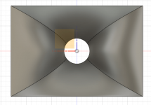
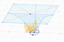
This is a quick sketch of two spline profiles lofted between a circle to a rectangle. If you want the shape to be more specific then you need more guide rails to constrain the loft.
Attachments
I skipped the obvious: a necessary mouth piece for transition from rect to circ, but as short as possible.
Maybe that doesn’t make it sampler though.
Maybe that doesn’t make it sampler though.
I see now that I probably want to use the ST260-30 with BMS 5530ND... the download has a .step but not a .stl file. Is there any difference when sending this to a printer? JLCPCB accepts both. Viewing the 3D models using JLCPCBs, the step looks coarser...
//
//
Attachments
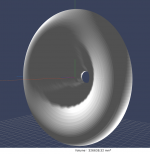
The STEP file is in fact independent of resolution - it's an ideal description of the object, and contrary to the STL file it's intended for a further work in a CAD (which then can result in a STL file of some fixed output resolution). To print or visualize a STEP file, it must first be interpreted in finite element terms (as is the STL file a set of triangles). That's what you are looking at and it's a question how they (JLCPCB) do that and whether the visualization matches the actual printed model. I would assume the printed model would be much smoother in the end but you should check (or make your own STL file from the STEP file - e.g. the mounting holes are still missing).
Last edited:
I see - thanks! I suppose it will be possible to drill the holes myself without too much effort!?
//
//
YesJokerbre, are these file still available?
- Home
- Loudspeakers
- Multi-Way
- Acoustic Horn Design – The Easy Way (Ath4)