Thanks, Eric. I thought I would safe myself that work. Got the cable, you have handy p/n for both connector ends?
You may use for instance TE connectivity P/N one 5-747909-2 + one 5-747908-2 + two 5748676-2 assuming male and female contacts at each end. but others Mfrs would do as well if you have a preferred one.
Got a PCB set and already assembled the PSU board.
@Eric06, that documentation you have put together for the new type power supply and shunt regulators is award winning! Thank you for that.
Thinking of using for analog two Tamura 3FD-448 and for digital Tamura 3FD-516 (for 5V relais Kemet EC2-5NJ), per trafo voltage selection sliders C&K V80212MA08QE and a Schurter 4301.3211 power entry module. Need to fabricate a neat pc board for those to finish up the PSU.
Found this DB15 male/female 1.5m long cable, looks like it might be used for the power supply to amp connection. Not sure what AWG are the wires inside, looks pretty standard though. Anyone any objections?
Last edited:
Yes I do have 4 other boards left, PM if you are interestedvery interesting!
do you have more of them?
Hi.
Does anybody have a SMT32 microcontroller left please?
Is only the SMT32F446 compatible or can any STM32 (LQFP100) be used?
example:
STM32F405, STM32F427, etc...
Thank you.
regards
Does anybody have a SMT32 microcontroller left please?
Is only the SMT32F446 compatible or can any STM32 (LQFP100) be used?
example:
STM32F405, STM32F427, etc...
Thank you.
regards
Hello,Hi.
Does anybody have a SMT32 microcontroller left please?
Is only the SMT32F446 compatible or can any STM32 (LQFP100) be used?
example:
STM32F405, STM32F427, etc...
Thank you.
regards
In theory the STM32F4 are compatibles pin to pin on the same package so it should be ok but double check the pinout to make sure.
But the main problem here is the FW if you want to use it for the UGS Muse as it is built for the STM32F446, so I would have to rebuild it for the device you choose.
Let me check if I still have some F446 in my personal stock.
You have some difficulties to buy this part online?
thank you Alex.
OK, so I will try to find a STM32.
At the moment there are no STM32F446 available on the "normal places" due to this chip-crisis...
Maybe you have one spare?
Thank you.
OK, so I will try to find a STM32.
At the moment there are no STM32F446 available on the "normal places" due to this chip-crisis...
Maybe you have one spare?
Thank you.
Guys, are you using 100nF or 100uF caps for decoupling the relais coils on the preamp boards? There is a note in one of the BOMs that 100uF have been tested but the BOM contains the 100nF caps. Appreciated your help. Thanks!
Anyone has schematics or PCBs, gerbers or any hints for using/connecting a 2nd encoder?
I can see gionag made some PCBs, unfortunately I can't find any gerbers posted. Thanks for any help.
I can see gionag made some PCBs, unfortunately I can't find any gerbers posted. Thanks for any help.
Gionag, I would be interested in your adapter board, hope you could help me out for the 2nd encoder. Thanks!
Anyone has a p/n for JP5?
Are all caps 10nF and all resistors 10k?
Attachments
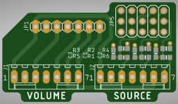
Single row male/female pin strips would do the job for JP1 and JP5, I guess.Gionag, I would be interested in your adapter board, hope you could help me out for the 2nd encoder. Thanks!
Anyone has a p/n for JP5?
Are all caps 10nF and all resistors 10k?
If gionag or someone can help me with that board would be great, otherwise need to fabricate one myself. I guess the flipside of the board must be GND and one pad of each of the caps goes to GND and then to pin12 of the spare I/F. Using 10k resistors and 10nF caps, 0805.
Including the other layer (in green) with GND, adapter looks like this.
Pins 2 and 4 of P4 "Encoder and LED I/F" connected to GND as well.
Pins 2 and 4 of P4 "Encoder and LED I/F" connected to GND as well.
Attachments

Last edited:
schematics are public ... made some pcbs for me. Everything else is only diy. Dont want to share gerbers files, etc... If anyone is interested, I have permission from Papa to make a copy for myself UGS V6.
Made some modification, position of components. First is Muse attenuation, second is UGS module and last is buffer. SOUNDS GREAT. THX people...
Made some modification, position of components. First is Muse attenuation, second is UGS module and last is buffer. SOUNDS GREAT. THX people...
- Home
- Amplifiers
- Pass Labs
- UGS-muse preamp GB