Gionag, I have a new binary for you to beta try.
It should improve the relay problem you had.
Will send you by email tomorrow.
It should improve the relay problem you had.
Will send you by email tomorrow.
Gionag, I have a new binary for you to beta try.
It should improve the relay problem you had.
Will send you by email tomorrow.
Oh !
thanks, as always, eager to try it out 🙂
i will report right after the outcomes... i think you already have my email.
Have a nice day !
Hi everyone
As the construction of my UGS Muse preamplifier sped up I’ve got a question about the power amplifier.
Do you have any experience with other systems apart from UGS UP? Which amplifiers work well with UGS Muse?
Maybe First Watt Aleph J or maybe something else.
Which devices your UGS Muse are connected to?
And one more question. Does using only two encoders instead of six buttons limit the functionality of the preamplifier? Are there any disadvantages of using a VFD display instead of two OLEDs?
greetings
Zbyszek
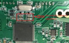
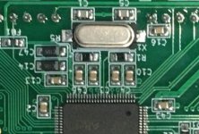
attention
Incorrectly soldered capacitors C10, C4, C3, C46!

It should be like this:

Yesterday I soldered my mcu board and today I uploaded the firmware successfully(the last version) and after that powered it up shorting sw1 and sw2 pins on the encoder connector. To my surprise the oled displays didn’t go on. Doing a few attempts to short sw1 and sw2 for different amounts of time(from 1s to 5s even more) the displays went on but displaying small pixels and turning on/off aleatory. Now they don’t start at all.
In bootloader mode the mcu draws ~30ma and in application mode it draws ~17ma.
I tried also to upload older versions of fw but with no luck, the issue is still there.
I checked also x1 and it’s working.
Can anyone suggest what else should I check?
Incorrectly soldered capacitors C10, C4, C3, C46!
It should be like this:
Attachments
Hi all, anyone can share a link to the gerber files, couldn't find those. Thanks much.
that's because there's none.
The pcbs was only acquired by Group Buy. A year ago i made the very same question and then, because there's other that was interested Alex_twn made it happen again.
Not sure if he will do it again, but it is worth asking 🙂
A quick question for Alex || Eric.
I was taking a peek of the inner working of the input matrix.
By schematic, seems that GND is "switched" by relay. i think that in order to make the input "balanced" vs "unbalanced".
But :
as the connectors used for inputs are NC3FAV-1 (looking at the bom). They have pin1 linked with ground, ground is taken from a lip inside the plastic eyelet that makes contact with the screw. As all the screws touched the rear panel (that usually is made of some conductive material, in my case... alluminium).
Doing so, the chassis makes a "bridge" between each and every pin1 of the XLR (and then, also with the grounds of the RCA's).
maybe i am totally wrong, but when you ground one input, let's say to make input 1 "unbalanced" then all the inputs became grounded despite the other relay settings, effectively making the whole preamp inputs unbal.
Is that correct or i have mis-understood the whole situation ?
The information on the French thread about the first UGS preamplifier may be helpful.
<<UGS All Inclusive - Montage - recap page 1 - 16/11/2007 - Page 4>> - 29861708 - sur le forum <<Amplis et Preamplis>> - 1056 - du site Homecinema-fr.com
(page4)
Does that also apply to UGS Muse.
<<UGS All Inclusive - Montage - recap page 1 - 16/11/2007 - Page 4>> - 29861708 - sur le forum <<Amplis et Preamplis>> - 1056 - du site Homecinema-fr.com
(page4)
Does that also apply to UGS Muse.
The information on the French thread about the first UGS preamplifier may be helpful.
<<UGS All Inclusive - Montage - recap page 1 - 16/11/2007 - Page 4>> - 29861708 - sur le forum <<Amplis et Preamplis>> - 1056 - du site Homecinema-fr.com
(page4)
Does that also apply to UGS Muse.
Oh ! thanks,
that will confirm my findings (and my overlooks 😱)
So to fix that, is enough to remove the "link" bridge on the FAV3-1.
for the outputs i think no fixes are needed as the connector has the shielding pin carried separately, and then it connects to earth correctly ( i think the "original" UGS-AIO used a different connector, that had, as inputs, the earth peg and the pin 1 connected at the the connector).
I am not sure if I am the only one that hasn't spotted earlier this "problem"... but maybe, if alex or eric confirms, will be useful to state it clearly for who are making (or has already made) the assembly !
It's an easy fix, just a little tedious to remove everything again 🙂
Last edited:
A quick question for Alex || Eric.
I was taking a peek of the inner working of the input matrix.
By schematic, seems that GND is "switched" by relay. i think that in order to make the input "balanced" vs "unbalanced".
But :
as the connectors used for inputs are NC3FAV-1 (looking at the bom). They have pin1 linked with ground, ground is taken from a lip inside the plastic eyelet that makes contact with the screw. As all the screws touched the rear panel (that usually is made of some conductive material, in my case... alluminium).
Doing so, the chassis makes a "bridge" between each and every pin1 of the XLR (and then, also with the grounds of the RCA's).
maybe i am totally wrong, but when you ground one input, let's say to make input 1 "unbalanced" then all the inputs became grounded despite the other relay settings, effectively making the whole preamp inputs unbal.
Is that correct or i have mis-understood the whole situation ?
You can use the Neutrik NC3FAV2 as it does not connect chassis to pin1/ground.
The NC3FAV2 has the chassis contact on a separate 4th pin (which you can use or not, i.e. strip off if there is not a 4th hole for it on the PCB; chassis connection will then go via the chassis to the star ground where the chassis is connected to), the three main pins are the same as on the NC3FAV1.
I only use the NC3FAV2 in super symmetry setups and separately take care about the chassis connection, i.e. it connects only centrally to the star ground, where also IEC inlet Earth goes to and circuit ground via a 10R resistor as well).
Last edited:
Anyone know, can the GR version of the 2SK309 and 2SJ109 be used as well in the UGS3 modules of the GB? Or is the BL version a must? Thanks.
They should be fine. Probably adust drain load upward to a slightly higher resistance and/or decrease the source degeneration.
One remark on the used Neutrik connectors NC3MAV and NC3FAV1 - they utilize a plastic ring on the front and the only contact they make with the chassis for shielding is through the one mounting screw.
The Neutrik NC3MBV-B and NC3FBV1-B are the same connectors, but with a metal ring on the front allowing for better contact with the aluminum panel and a far better connector shielding. Normally on a regular amp this probably wouldn't matter, but since the UGS is about over engineering I thought I'll share this.
The -B in the end stands for black, without it the metal ring would be nickel so perfect for all non-black anodized, raw aluminium panels (the NC3MAV/NC3FAV1 are black plastic only).
As I would be mounting the IRF610 and IRF9610 of both shunt regulators directly to the bottom aluminium plate of the preamp, I will be using Aavid 4170G ceramic insulators and Aavid 7721-10PPSG PPS washers for proper insulation of the TO-220 case and the stainless steel bolt (tightened to 0.8 Nm). Might be overkill, but I like it that way 🙂
I might put the MOSFETs as well on a vertical 10mm thick aluminium divider plate which is tightened to bottom serving additionally as a shield to the preamp section in the back of the case.
I might put the MOSFETs as well on a vertical 10mm thick aluminium divider plate which is tightened to bottom serving additionally as a shield to the preamp section in the back of the case.
i meant that if somebody is crazy enought and wants to replicate 1:1 what i did I can supply all the custom mechanical parts to mount on the Slim-Line case.
I have full and free access to a fiber laser to make the engravings/lettering and to a 3-axis cnc to work on the alu parts (knobs, frontplate, heatsink).
i will not share plans, but i can do all the work and sell with a price of cost, withnout any premium or surcharge. i don't want to make a profit from it.
at the moment the case is still missing the anodization... a medical situation has stopped me from sending to the anodizing facility. i will recover next year.
Gionag, you got PM
- Home
- Amplifiers
- Pass Labs
- UGS-muse preamp GB