Craig, thank you a lot for your listening impressions and sound descriptions !
One difference between the ACA and the Aleph 30 is that the ACA uses a JFET in the front end, whereas the Aleph 30 uses MOSFETs.
The Aleph 30 is still single-ended, in fact you can adjust the active Aleph current source to behave like a traditional current source, and then it is no different from a standard single-ended amp.
I suspect the difference you hear in microdynamics and micro-timbral shifts might be caused by the different front ends.
A number of years ago, I built a Mini Aleph (on BrianGT boards) as one of my first amps. Schematics are exactly like an Aleph 30, but with one pair of output devices. I later converted it into an Aleph J (still one pair of outputs) by modifying the front end to work with a pair of J74 JFETs.
And the main differences and improvements I heard with the conversion were exactly in the areas where you described the ACA and your 300B as being in favour - microdynamics and micro-timbral shifts / "continuousness". It was just a more refined amp with the JFETs, less "coarse".
So, that might be something to try for an encore ... 😎
Best regards, Claas

Craig,If SEPP has no crossover point, would like to know the architecture. Can you describe it?
Again, it is just my Internet reading, but have read that whenever the architecture is push-pull, then the positive and negative portions of the waveform will always have CP. Emotiva started using so-called "high-bias" class A (in my XPA-1s) that simply leave the push/pull transistor sets on all of the time. So they continue to trade off power portions, but do so without the turning on and off in the A/B architecture. And because they are always on, that lessens the CD because the transition is minimized.
Let me know.
I can explain it but Hugh Dean, designer at AKSA does it much better:
https://www.diyaudio.com/community/threads/discussion-of-alpha-nirvana-operation.346289/post-5990167
And
https://www.diyaudio.com/community/threads/discussion-of-alpha-nirvana-operation.346289/post-6098757
Another thing you will see is these SE designs never double their wattage into a 4 ohm load, and depending on bias current amounts, it can be less. In example, the Aleph J is about 13-15 watts into 4 ohms. The Aleph 30 does better (with more devices) at 40 watts/4 ohms and the Aleph 60 is best (but needs large heatsinks, fan, or liquid cooling) for 100 watts/4 ohms.
Best,
Anand.
Last edited:
Anad: Thanks. Found an almost identical discussion here at Wikipedia and think it is now somewhat clear -- along with the "seemingly contradictory" label:
https://en.wikipedia.org/wiki/Push–pull_outputYour link to Nelson's Zen Variations Part 2 above also helps explain the Aleph efficiency advantage.
6L6 was kind enough to have already provided me with the Aleph J boards by ZenOn and I should, certainly, build them and compare them with the Aleph 30. Will be spending a few days just to listen to the current Alephs that are sounding superb.
Have also put my testing equipment together and have all of the tools to complete the calibration outlined in Randy's excellent build guide. Understanding the SEPP concept seems essential to making sense of what you are doing with the calibration process, right?
Craig,
I don't know if understanding the SEPP concept (or Zen Variations Part 2) is essential but it certainly helps 🤓! Randy's stepped instructions for setting the AC gain on page 4 is essential though! Having a sinewave generator is important and an oscilloscope or multimeter (voltmeter) across the source resistors is a must.
My Aleph 60 is still in the planning stages. I think a 4U/500 is a bare minimum for a stereo version. I'm hoping it hits the 100W/4 ohm ball park in my build (for bragging rights, etc...etc...😎).
Oy vey!
Best,
Anand.
Last edited:
Well there are some obvious questions with the page 4 instructions.
You setup your signal generator with 16vrms at 100hz into an 8R load -- will be using a 3-watt 8R resistor across the speaker terminals, right?
Then you measure each V- source resistor with the AC Gain Jumper removed, copy down the mv values and halve them.
Then you reinstall the jumper and measure the same values. You want them to be 1/2 of the non-jumped values but there is only one P2 to adjust. So you adjust them so that the jumped total of R40-R43 is 1/2 of the non-jumped total? Not clear here. One adjustment affects all 4 resistors, right?
On page 19 you collect values for each current, then each output mosfet. Where? On the mosfet itself? Or on its connected resistor? And the adjustment here is made by P3? Again, how can you adjust multiple values with a single trimpot? Do you adjust for the Total mosfet values? And when you make an adjustment with (I guess) P3 does it affect both current and output mosfets?
Checked the supplied DIY link and it just provided the same Nelson Pass info.
Does P1 affect any of these values? Made quite a few clockwise turns to get the offset down to the 20 mv level and it is now different than the original 242R value. Should they be adjusted counterclockwise back up towards 50mv to approximate the original R setting?
Last edited:
I'm sure Randall will pitch in at some point but I see you have some interesting oversights.
Let's start with the 1st.
What is 16v RMS in watts? How did you conclude that you needed a 3 watt resistor? <Hint> You will absolutely cook your 3watt 8ohm resistor if you run 16V RMS through it.
And...more importantly....is 16v RMS the necessary voltage you need to test at, or do you think NP is just giving you an arbitrary value since he is trying to illustrate by example? Do you think testing at 2.8V RMS is a possibility? How many watts is that into an 8R resistor? These are all good questions to ask.
You measure the individual mV values down across each of the source resistors, and jot them down. Did he ask you to add them in the instructions? Adjusting P2 should adjust the values of the aforementioned source resistors simultaneously.
Each source resistor is representative or paired with it's respective MOSFET (as seen on the schematic). When you measure the voltage across the resistor and divide the value of said resistor you obtain the current; V/R = I. See post 118. P3 adjusts output stage current. See and study page 3 in your design manual for details, under 'Bias Current Measurements.' What does Randall say there?
P1 affects output DC offset and is directly related to the matching consistency of the input differential pair of MOSFETS. These MOSFETS are already matched, courtesy of Randall so that helps...A LOT. You can adjust P1 once everything else is set (i.e. P2 and P3) and the amp has been good and warm for about 1 hour. Get it below 50mV and you are good. If you are patient, I am sure you can drop it further but it should make little difference or harm to your speakers. Some diy'ers get emotionally jubilant about achieving an offset of +/-1 mV for some reason!
Best,
Anand.
Last edited:
And to clarify, I would set the output stage bias current first with P3 while making measurements across the source resistors, let the amp warm up a little and then look at the DC offset at the output speaker bp and adjust P1 for minimal offset.
When that’s all set and done I would then test and check the AC current gain as described by NP and adjust it. It’s likely you are pretty close already since Randall used the original values from the design.
You can then go back and double check the output current and dc offset again if you like as I imagine the output current and dc offset have a nice interplay as the amp reaches thermal equilibrium.
Best,
Anand.
Anand: Do not want to "go fish" with these settings. If the calibration instructions cannot be made sensical then I will pass. If the Vrms should be something other than 16 then the instructions should state what the value should be. Am tired of guessing and am not going to reinvent the testing procedure to fix unclear instructions. That is not the requirement of the builder.
Anand: Do not want to "go fish" with these settings. If the calibration instructions cannot be made sensical then I will pass. If the Vrms should be something other than 16 then the instructions should state what the value should be. Am tired of guessing and am not going to reinvent the testing procedure to fix unclear instructions. That is not the requirement of the builder.
No worries.
The Power equation is:
P(watts) = V(squared)/R; V is in RMS in this example. R is in ohms. An illustrative explanation.
P(watts) = 16*16/8 = 32 watts RMS. That means if you were to input a signal into the Aleph 30 to generate 16V rms on the output across the 8 ohm resistor you would need a 32 watt resistor bare minimum. In fact you need a resistor that can handle at least double or triple that because the resistor will heat up considerably over a short period of time. I use 100 watt 8 ohm test resistors I get from Parts Express for example.
I am not planning on testing at such a high output swing voltage initially but will test at various other voltages to see if the AC gain setting methodology that has been stated on page 4 works. Nelson Pass I believe used 16V rms as just as an example. Perhaps 1 watt, 5 or 10 watts will be enough. And of course I can use an oscilloscope to measure the sinewave on the output instead of an AC voltmeter. And even try different frequencies instead of the suggested 100Hz which I believe Nelson stated because he knows that cheap/inexpensive AC voltmeters (used in this particular example and are accessible to most newbie diy'ers) are most accurate measuring at less than 1khz, and particularly less than 400Hz. With a 70Mhz scope I can measure at various frequencies.
Enjoy the music.
Best,
Anand.
Last edited:
Hi guys. Is Aleph 30 workable on 18 to 20v rails? My 18v trafo along with my intended capmx psu loaded up is only giving me 18v. I could probably get to 20v by changing the mosfet on the capmx.
If reduced power output is the result I can probably handle that, but I'm new to solid state and class a and so the implications of lowering the rails is something I am not experienced with.!
Thanks
If reduced power output is the result I can probably handle that, but I'm new to solid state and class a and so the implications of lowering the rails is something I am not experienced with.!
Thanks
Jim,Hi guys. Is Aleph 30 workable on 18 to 20v rails? My 18v trafo along with my intended capmx psu loaded up is only giving me 18v. I could probably get to 20v by changing the mosfet on the capmx.
If reduced power output is the result I can probably handle that, but I'm new to solid state and class a and so the implications of lowering the rails is something I am not experienced with.!
Thanks
Look up threads and the schematic of the Aleph-M to get suggestions on the changes needed. You’ll essentially end up with 10-15W of power. Also, our very own Claas (@chede) had built something similar as I recall. One thing is for sure though, somebody has already built it ;-)
Best,
Anand.
Hi Jim,
no changes needed.
I had my Aleph Mini (basically an Aleph 30 with just one pair of output MOSFETs) on 19V rails initially. This will give you somewhat less power into 8 Ohm speakers than the higher rails, but it still sounded great to my ears. A lot of folks run their standard FirstWatt diy PSUs at 22-23V rails also anyway ...
And on the other hand, the lower rails make for less heat dissipation in the output MOSFETs. You can use this to crank up the bias more, which will give you more power into 4 Ohms, and possibly better sound as well ...
I did run mine with 19V rails at 2.2A bias (because I had it in a big chassis, similar to 4U/400), and actually slightly preferred the sound to 24V / 1.9A ... 😎
So, just go for it ! 🙂
Regards, Claas
Edit / P.S.: I wouldn't go much lower than 18V rails. At even lower voltages, the non-linear capacitance of the MOSFETs starts to get in the way of good performance / sound ... but this is being talked about in the Aleph Mini discussions as well.
Thankyou. I really didn't want to be 'that guy' to start their infancy in the Pass section of the forum by asking if I can take shortcuts. This isn't my slant! The amp i was gifted by Randy deserves its best. And I shall give it all I can muster, to the best of my financial and technical limits, which are both somewhat modest.
Hi Randy,
I think a little correction is needed in the BOM of the Aleph 60.
Based on the BOM, R28-R39 should be 221R 1/4W, but at the same time R36-R43 1R 3W - there is an overlap for R36-R39.
I think, only R28-R35 should be listed as 221R (instead of R28-R39), because R36-R39 are big ones on the board, so they can´t be 221R 1/4W.

Cheers
I think a little correction is needed in the BOM of the Aleph 60.
Based on the BOM, R28-R39 should be 221R 1/4W, but at the same time R36-R43 1R 3W - there is an overlap for R36-R39.
I think, only R28-R35 should be listed as 221R (instead of R28-R39), because R36-R39 are big ones on the board, so they can´t be 221R 1/4W.
Cheers
The next one 😀
R15-16 = 221R 1/4W but
R16 = 392 R 1/4W
Which one applies?
The circuit diagram says R16 = 392 R, the BOM says both 😀 the build guide says choose the values from BOM 😛
So... 🤔 😵
R15-16 = 221R 1/4W but
R16 = 392 R 1/4W
Which one applies?
The circuit diagram says R16 = 392 R, the BOM says both 😀 the build guide says choose the values from BOM 😛
So... 🤔 😵
Good eye!The next one 😀
R15-16 = 221R 1/4W but
R16 = 392 R 1/4W
Which one applies?
The circuit diagram says R16 = 392 R, the BOM says both 😀 the build guide says choose the values from BOM 😛
So... 🤔 😵
I will make a new revision of the doc on Post #1 with these edits.
The 221R's should read "R9-12, R15-16, R28-35 + Exp. PCB gate Rs", not "R9-12, R15-16, R28-39 + Exp. PCB gate Rs"
R16 = 221R. I had it double entered, copy/paste.
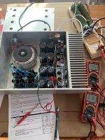
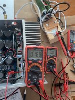
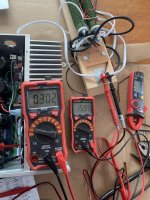
I tried the AC Current Gain procedure and figured it out. I tried at 10V and 16V into a big dummy load resistor setup. (16R 120W resistors in parallel).
At first, my meter was reading DC, so the readings didn't change at all with the jumper in or out. OOPS, change it to AC. I had to turn the pot to get to the 50% figure, it was originally a little low. I had to adjust my input voltage just a little when I put the jumper in to get the output to the same value (10 or 16V).
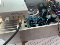
My test setup:
Input
Akitika 1kHz sine wave generator. I grabbed this because it's battery-powered and simple to grab and use on my dining room table. My alternate would be a signal generator that plugs in. One could also use a sine wave from a phone, CD, etc.
Output
2x 16R 120W dummy load resistors in parallel for 8R load to amp.
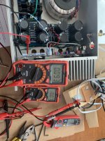
Measurement
1 DMM on the dummy load resistors measuring AC volts
1 DMM on the source resistors using clips measuring AC Volts
It turns out my DMM's are OK to measure 1kHZ AC voltage. This may not be true for all.
I could imagine simply measuring one of the resistors instead of all 3 is fine. You're looking for a 50% ratio when the jumper is in or out. That ratio should track to all the source resistors. This is not the same test looking for total DC current and how well it's spread across the MOSFETs.

/
At first, my meter was reading DC, so the readings didn't change at all with the jumper in or out. OOPS, change it to AC. I had to turn the pot to get to the 50% figure, it was originally a little low. I had to adjust my input voltage just a little when I put the jumper in to get the output to the same value (10 or 16V).
My test setup:
Input
Akitika 1kHz sine wave generator. I grabbed this because it's battery-powered and simple to grab and use on my dining room table. My alternate would be a signal generator that plugs in. One could also use a sine wave from a phone, CD, etc.
Output
2x 16R 120W dummy load resistors in parallel for 8R load to amp.
Measurement
1 DMM on the dummy load resistors measuring AC volts
1 DMM on the source resistors using clips measuring AC Volts
It turns out my DMM's are OK to measure 1kHZ AC voltage. This may not be true for all.
I could imagine simply measuring one of the resistors instead of all 3 is fine. You're looking for a 50% ratio when the jumper is in or out. That ratio should track to all the source resistors. This is not the same test looking for total DC current and how well it's spread across the MOSFETs.
/
Attachments
-
 B0478270-2F2B-45D0-B09E-E04EC97BA806.jpeg556.6 KB · Views: 198
 -
 40570F3C-BE6C-40A8-AB4F-767E2E58953C.jpeg524.8 KB · Views: 197
 -
 628799AE-D916-496B-9D85-E45FBEBC86A7.jpeg382.1 KB · Views: 171
 -
 4D0AE9D5-4939-4E83-97A6-B74D2712DC7F.jpeg511.6 KB · Views: 168
 -
 43984C72-5AE7-4594-8C5F-9ABF8709FBC2.jpeg509.1 KB · Views: 180
Darn those resistors are huge.
How many turns did it take to get to 90mV? Or better yet how far off was the setting with a jumper in and standard values? Was it worth the effort/cost?
How many turns did it take to get to 90mV? Or better yet how far off was the setting with a jumper in and standard values? Was it worth the effort/cost?
I didn’t count. 2 turns? 1.3? 3.8? Not a lot, but it wasn’t just a little 1/8 turn nudge either.How many turns did it take to get to 90mV? Or better yet how far off was the setting with a jumper in and standard values? Was it worth the effort/cost?
The cost (for me) was 2 pots because I had the dummy load resistors, signal generator, and dmm’s on hand. And it took only a few minutes once I figured out what’s what. The amps sounded phenomenal before. I will have them back in the system in 2 days after a pair of ACAs I repaired for a guy are done with a shakedown run. Which is to say I guess I won’t really be able to do a fair before/after test.
Thanks a bunch Randy. You should make post 237 a sticky/link on the 1st page of the thread for all to view. That way we can direct folks there when they have a question about setting AC current gain.
I also have an Akitika unit and it is an excellent low distortion oscillator for testing purposes. Very simple to build and highly recommended.
Best,
Anand.
I also have an Akitika unit and it is an excellent low distortion oscillator for testing purposes. Very simple to build and highly recommended.
Best,
Anand.
- Home
- Amplifiers
- Pass Labs
- Classic Aleph Amplifier for Modern UMS Chassis Builder's Thread