I powered up just the heater supply for this board with no tubes as my initial test. I'm getting ~7.6VDC from H+ to G, and 0V from H- to G. The transformer is a Triad VPT12-2080: https://www.mouser.com/datasheet/2/410/VPT12_2080-781423.pdf. I've wired the inputs in parallel as per the data sheet as I have 115VAC power. I've wired the output in series for 12VACT CT, as per the data sheet. I'm getting 6.8VAC between the Black or Yellow secondary wires at the Red/Orange pair, and 13.6VAC across the Black and Yellow wires. Input power is set to 115VAC with a variac.
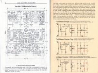
I configured the power supply in the Full-Wave Center-Tap configuration in the attached scan. Black and Yellow transformer secondary wires go to the A C connections, and the Orange/Red wires go to the CT position. I omitted D10, D9, C11, and C12, as per the diagram for the Full-Wave Center-Tap configuration.
The fact that I am getting a stable voltage that is approximately 1/2 of what I am expecting makes me think I have misunderstood some aspect of the power supply / transformer configuration. Either wiring the transformer incorrectly, or configuring the power supply incorrectly. But, I'm not sure what exactly I've done wrong.
Attachments
Last edited:
Should measure H+ to H- . I think you would get 12v-12.6v,. Even set at 115v but the outlet 120v, you may get a little bit more at secondary.as 13.6vAC
You must run Voltage Double because the PT doesn't have center tap
low TOROIDAL voltage 6.3v shouldn't be a problem except high voltage with TOROIDAL, you may encounter hum as hell unless you keep the TOROIDAL far away from the tubes like 6 inch.

You must run Voltage Double because the PT doesn't have center tap
low TOROIDAL voltage 6.3v shouldn't be a problem except high voltage with TOROIDAL, you may encounter hum as hell unless you keep the TOROIDAL far away from the tubes like 6 inch.
Last edited:

H+ to H- reads the same as H+ to G. H- to G reads 0.
The data sheet says "Output Voltage: Series: 12VAC CT @ 2.08A". Does that not mean that if I connect Black and Yellow to the A/C inputs and connect Red and Orange to the CT input, I should have center-tap? Or do the primaries and secondaries have to be run in the same configuration?
The data sheet says "Output Voltage: Series: 12VAC CT @ 2.08A". Does that not mean that if I connect Black and Yellow to the A/C inputs and connect Red and Orange to the CT input, I should have center-tap? Or do the primaries and secondaries have to be run in the same configuration?
I am not sure but that creates 12v in series.. H+ and H- don't connect with GND signal.
As I remember John said you need at least 6.3v/3.5A AC in order to get 12v/2A DC So when you double for 4A, it's fine. no problem.

As I remember John said you need at least 6.3v/3.5A AC in order to get 12v/2A DC So when you double for 4A, it's fine. no problem.
I rewired in voltage doubler configuration, and I'm getting 12.56VDC across H+/H- now. Makes sense that if I was getting half the expected voltage running "voltage doubler" would fix it. I still don't understand the transformer nomenclature, but that can be for another day.
Thanks a lot!
Thanks a lot!
If you put R11 : 1.07k, you would get 12v
Yeah, that's the current value.
I guess because of 13.6vAC. I think it will drop at 12.2vDC with tubes. Should be alright. at -/+5%
I guess because of 13.6vAC. I think it will drop at 12.2vDC with tubes. Should be alright. at -/+5%
It will go up when I connect raw AC power. I have it at 115VAC with my variac, but my outlets produce ~122VAC. I suppose I could adjust R11 if it drifts too high.
Not that much unless you get 125-130v. The formula below. Do not adjust R10
V = 1.25 (1 + R10/R11)
V = 1.25 (1 + R10/R11)
I'm having the same problem with the B+ supply. I'm only getting ~20VDC at the B+ tap to ground in the center of the board. I've tried configuring it as center tap and parallel with the same result.
This is the transformer for the B+ supply: https://www.mouser.com/datasheet/2/410/VPT230_110-781486.pdf
I'm not an idiot, but I'm also at the point where what I understood to be the correct way to setup the power supply/transformer connection isn't producing the expected results, and I've tried all the troubleshooting steps I can think of. I would rather seek help sooner rather than later, considering this is a 300V circuit.
I'm not an idiot, but I'm also at the point where what I understood to be the correct way to setup the power supply/transformer connection isn't producing the expected results, and I've tried all the troubleshooting steps I can think of. I would rather seek help sooner rather than later, considering this is a 300V circuit.
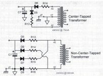
Again, the PT doesn't have C.T. so you need to to create one.
I'm still confused about this. The data sheet says "Output Voltage: Series: 230VAC CT @ 0.11A Parallel: 115.0VAC @ 0.22A". Isn't that center tap? If not, then what is?
I've looked at various Triad transformers before and always thought the same way you did OP. The datasheet says CT after the voltages. But looking again at the wiring for series, I think they mean, "Connect to black & yellow" meaning AC is applied to these two wires and then "Jumper red & orange" meaning connect these to each other and insulate them. That being said, I don't think you need a voltage doubler for the heaters or a CT B+. It looks like the board is set up for full wave bridges
Yooo! This was exactly the advice I needed! I tried it that way and got both power supplies running as full wave bridges. Thank you so much! I felt like I must be missing something, but I didn't know enough to know what I was missing. Thank you very much! I'm up and running now!
No problem. I'm glad you started this thread, as I've been looking at these Triad datasheets wrong until you brought this up. What tubes did you use? Let's see some pics!
I haven't totally decided on tubes yet. My plan is to do 12sl7 for the drivers for the gain, and 6bl7 for the output for the low output impedance. I have a pair of NOS '50's era GE 6bl7's that I'll probably use. I ordered a couple options for the drivers, a pair of NOS RCA tubes from the 50's and a pair of Sylvania mil-spec from the 40's, but I misread the auction and they turned out to be 12sN7's. I plan to listen to the RCAs and Sylvania's (which should work without modification, I think) and go from there.
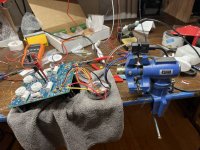
It'll be some time yet before I have finished unit pictures, as I have to fabricate a case for it still. But here's a test bench pic from today (dents from where I was banging my head on the table are out of frame).
It'll be some time yet before I have finished unit pictures, as I have to fabricate a case for it still. But here's a test bench pic from today (dents from where I was banging my head on the table are out of frame).
Attachments
- Home
- Amplifiers
- Tubes / Valves
- Heater power supply producing ~1/2 expected voltage - Aikido All-In-One line stage