Hi Stephane!
What is your latest(tested) mini-board! Is it 1.2 15/ 16?
I am busy ordering boards atm. Btw they look beautiful anyhow. I am curious hearing them!
Ed
What is your latest(tested) mini-board! Is it 1.2 15/ 16?
I am busy ordering boards atm. Btw they look beautiful anyhow. I am curious hearing them!
Ed
yes Stef that is the first plan for me to remove the existing resistors and short them 👍Hi manniraj,
Just shunt the resistors of your LT4320 PSU.
Regards,
Stef.
yes Stef that is the first plan for me to remove the existing resistors and short them 👍
If your power supply does not work with the Q17, you can always buy this PCB. It's not expensive and it works very well.
https://fr.aliexpress.com/item/1005003750120634.html
https://fr.aliexpress.com/item/33004037072.html
Regards,
Stef.
Attachments
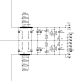
These psu boards seem to be similar to what Prasi laid out with 4 caps and optional resistors either a pair of BPR per side or using Panasonic 0.47R multiple ones underneath the PCB. I am using those psu boards as dual mono in my pass amps. I can use the same psu but remove the resistors and short them. Prasi psu boards are pretty good and robust 🙂
Q17 is a class B amplifier and I already mentioned that CRC should never be used in a class A/B or B amplifier
Tibi, can you briefly explain why PSU with CRC filter is not good for AB/B class amp?
Hi!
The 1.2 PCB is not yet available. I'm working on. Late February if all is fine. The 1.2 files on Github are only to show.
The current working (and available) PCB is 1.1.
Regards,
Stef.
Thank you for your answer.
I can not find any 1.1 Gerber. Will it be 1.1.4 for instance?
thanks,
Ed
II'll try to keep it short and simple - KISS. 🙂Tibi, can you briefly explain why PSU with CRC filter is not good for AB/B class amp?
Due class B operation that require high variation of current, resistor inside CRC filter will "see" a large voltage variation across him. Take Q17 where output currents may go form 0A to ~ 5A. A CRC filter with only 1 ohm resistor will see up to 5V modulation. The capacitor behind resistor will not help much and in fact will increase peak voltage.
Sonically this is translated in lazy sound, with poor dynamics and overall soft performance. Some people like this. Not me.
Same thing is happen with diode rectifiers. Voltage across each diode is modulated with load current. At 1A a Schottky diode is already at 0,6V voltage drop and at 5A is over 1V. Soft recovery diodes may go as high as 2V or higher at high voltage operation.
If you want a top performance amplifier ... I already mentioned what you should use.
Regards,
Tibi

Thank you for your answer.
I can not find any 1.1 Gerber. Will it be 1.1.4 for instance?
thanks,
Ed
Hello,
The 1.14 is the last version. If you wait one week, I'll will have PCB prototype of the 1.2. They are in the plane. If the prototype is ok, I'll publish the final 1.2 files asap. Some PCB of the first print will be available too.
Regards,
Stef.
I just found out the 1.2 gerber was allready in processing at the pcb factory. Could not undo it. So I wait and see how you continue with your board. A pity because I could have tried one of yours. Thank you for your offer and your work on the project!Hello,
The 1.14 is the last version. If you wait one week, I'll will have PCB prototype of the 1.2. They are in the plane. If the prototype is ok, I'll publish the final 1.2 files asap. Some PCB of the first print will be available too.
Regards,
Stef.
regards,
Ed
Hello Tibi,
You recommend this active bridge rectifier ?
https://evotronix.eu/main/
SALIGNY Standard

I use industrial diode bridges,
I surely have something to gain by replacing them.
Thx,
Julien
You recommend this active bridge rectifier ?
https://evotronix.eu/main/
SALIGNY Standard
I use industrial diode bridges,
I surely have something to gain by replacing them.
Thx,
Julien
Hi Julien,
Verify that pinout are ok with the yellow board.
FQA46N15 out of stock at Mouser. No date. 🤢
Good deal for those who may be interested. Mouser will have in stock on 02/25/2022 some Nichicon UKW 2200uF 63v.
https://www.mouser.fr/ProductDetail/647-UKW1J222MHD
Regards,
Stef.
Verify that pinout are ok with the yellow board.
FQA46N15 out of stock at Mouser. No date. 🤢
Good deal for those who may be interested. Mouser will have in stock on 02/25/2022 some Nichicon UKW 2200uF 63v.
https://www.mouser.fr/ProductDetail/647-UKW1J222MHD
Regards,
Stef.
@juju35135
Yes, Saligny Standard is my commercial design. A free THT version was posted by me in case you want to build yourself.
@stef1777
These days, almost any part is out of stock. My last mouser order was placed December 2021 and Saligny parts are postponed for march 2023.
I know big companies that are freezing their business due parts crisis.
Regards,
Tibi
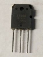
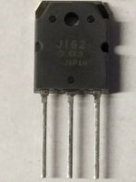
2SK1058 / 2SJ162 are lateral mosfet. These exhibit low transconductance. On other side, 2SK1058 / 2SJ162 are rugged and well regarded mosfets. As output drivers, these sound very well if you use easy to drive speakers with high SPL.
If you get these at very low price, you may adapt your PCB and use them in place of Q5 and Q6. No other schematic modifications are need.
Regards,
Tibi
If you get these at very low price, you may adapt your PCB and use them in place of Q5 and Q6. No other schematic modifications are need.
Regards,
Tibi
@juju35135
Yes, Saligny Standard is my commercial design. A free THT version was posted by me in case you want to build yourself.
@tvicol
Hi Tibi, I'm not familiar with SMDs...
When I have some extra money. I will buy you a pair of rectifiers, it will be enjoyable to support your company. 🙂
@stef1777
interesting parts, a new version of pcb in project !
Regards,
Julien
Last edited:
A quick update on my amp build. I am testing now using a 22vac 300VA trafo using a CRC psu of LT4320 but the resistors are shorted per the suggestion of Tibi. I am getting around +/-33vdc from the psu.
Now using a bulb tester for the initial power up the bulb goes down initially and then comes up fast with blinking and then glows optimally. I checked the DC rails and they drop to +/-10.5vdc with the bulb tester. But the red leds on the amp boards do not glow during the power up and I checked the polarity as standard longer leg to the circle and shorter leg to the square pad before soldering. Is this normal for the leds not to glow as the DC rails are low 10vdc using a bulb tester? I checked the voltage across R10/12 which are 47R/1W and its 2.89vdc and 3.12vdc which makes around 60mA current flowing. In this test I have shorted the input signal. And the offset shows around 0.5-1.2mV and hovering slowly closer to the 0mV.
Then with the bulb tester still in the mix, I put a 0.1R/5w resistor with the positive rail supply and checked the voltage across it which shows as 172mV. This seems to be high and hence the bulb is glowing rather than being dim.
Let me know any inputs as I feel the input stage is good with 60mA but not sure if the output stage is fine.
Thanks
Hi manniraj,
You need at the minimum 25Vdc (better 30v) on the rail to have the two LEDs ON.
If you use OPA1641 (JFET) and short input, use a 100R resistor to do this. Don't use a a wire.
Stef.
You need at the minimum 25Vdc (better 30v) on the rail to have the two LEDs ON.
If you use OPA1641 (JFET) and short input, use a 100R resistor to do this. Don't use a a wire.
Stef.
Last edited:
- Home
- Amplifiers
- Solid State
- Q17 - an audiophile approach to perfect sound