Hi all. I am building a new set of full range speakers and I'd like to get your thinking on using 4cu ft, 5cu ft, and 6.5cu ft cabinets as shown in the picture below. How obvious will the different roll-offs be?

6.5 is tough on WAF.
Anyway, I only build subs in SEALED boxes as the second order blends with room gain and you get as much bass as a ported box after you eq down the huge peaks you would get with any of those alignments. So, in situ, no difference.
You also have not looked at cone excursion and port diameters. I do not know that driver, ( found nothing in search) but to get a port large enough (5 is about right for a sub) it may be longer than you can make.

As I like Bach organ music, I would go for the 5ft3.
Otherwise, the 4ft3 is fine for almost all music.
Looks like you might try 3-3.5ft3.
Otherwise, the 4ft3 is fine for almost all music.
Looks like you might try 3-3.5ft3.
I do and she is wonderful about my hobby.Perhaps djn doesn't have a W! 😉
Cone excursion is +/- 1.5mm and the vent on all of them is .75” to 1.5”6.5 is tough on WAF.
Anyway, I only build subs in SEALED boxes as the second order blends with room gain and you get as much bass as a ported box after you eq down the huge peaks you would get with any of those alignments. So, in situ, no difference.
You also have not looked at cone excursion and port diameters. I do not know that driver, ( found nothing in search) but to get a port large enough (5 is about right for a sub) it may be longer than you can make.
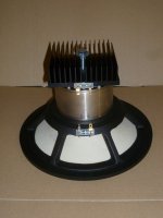
Is this some sort of PA speaker? 18 inch or something? What woofer is this?Cone excursion is +/- 1.5mm and the vent on all of them is .75” to 1.5”
Check your port velocities. See what they are with the correct amplifier power for whatever SPL you want. I find I hear the port with much more than half the SOP. You have WinISD. USE IT. Use all of it. Besides the port, look at the excursion it simulates as it goes below Fb.
Still, do not forget about room gain! All of those alignments will give a HUGE bump in the response you would have to EQ down. Now if you were using it outside that is a different story. You do not want a flat speaker in the simulation! On either end actually.
.75 inch port? Heck, I use a 1 1/4 on my desktops with a 3 inch woofer! The new ones with a 4 inch I am using a 2 inch to keep the velocity from "chuffing" only because I pick about 96 dB as my design peak.
Hint, my SUBS, which in room F3 around 25 Hz are only 1.5 cu ft. Critical Q sealed. 12 inch peerless drivers. In simulation, they look like F3 of about 60 Hz.

in a room i would use the 4cuft box i think, it has aroll of but the room modes will add bass, for outside i would use the bigger cab as there is no room gain.
Still no model so we can't see what you are talking about. Pictures don't have any TS parameters.
Hi all. I am building a new set of full range speakers and I'd like to get your thinking on using 4cu ft, 5cu ft, and 6.5cu ft cabinets as shown in the picture below. How obvious will the different roll-offs be?
If you play with an equalizer you'll find that we have a hard time hearing 3 dB difference down low, so anything audible will be due to how each energizes the room, but in general, better to choose the most power efficient alignment at 'x' desired tuning or based on the driver Fs if it's low enough for the app (Vas/1.44, tuned to Fs).
Hi GM, I understand the 3db not being not so audible but not sure about what you said after that. Could you restate it for the not so educated (me).
EBP is 37.8, Clearly designed for a SEALED box.
A 2 cu ft box gives an F3 of 77 Hz.
5W is the power limit not to exceed X-Max and it will give you 98 dB. Very loud. Really efficient driver.
77 may not sound low, but in a real room with room gain, that actually will cover most all music very well.
a 3 1/2 cu ft ported box does give you a 44Hz F3. A very short 3 inch vent would not chuff, but it really really should have a high pass filter on it. With a sealed cabinet, this driver does not need a HP to protect it. You would need EQ to reduce the hump around 60 to 50 caused by room gain.
How audible a change in eq is depends on the person and the frequency. A couple dB @ 200 Hz is not likely to be audible, but at 3000Hx, 1/2 dB will completely throw off the character of a soprano.
So you have different voltage settings to mess with the T/S parameters as per above if I understand it correctly.
I assume that would be the highest voltage setting from the FC supply. I would not build with too un-damped a response if you intend to mess with the FC voltage, as lowering it and therefore raising the Qt would make for a boomier alignment. Maybe design something with a smooth roll-off using the "semi-OB" data set, either sealed or vented. Be prepared for a large box of vented though. You could also tune lower as the Qt gets higher, though I'd advise sealed for the two leftmost parameter sets. Keep in mind any output impedance from the amplifier you intend to use and add it to the simulation under the signal tab in WinISD.
Are you still running your TD15M with copper-plated pole-piece extension?
Here you go. I used the T/S from the Vented box on the right.
I assume that would be the highest voltage setting from the FC supply. I would not build with too un-damped a response if you intend to mess with the FC voltage, as lowering it and therefore raising the Qt would make for a boomier alignment. Maybe design something with a smooth roll-off using the "semi-OB" data set, either sealed or vented. Be prepared for a large box of vented though. You could also tune lower as the Qt gets higher, though I'd advise sealed for the two leftmost parameter sets. Keep in mind any output impedance from the amplifier you intend to use and add it to the simulation under the signal tab in WinISD.
Are you still running your TD15M with copper-plated pole-piece extension?
GM means that if you're going to EQ, go with the alignment that gives the best power-efficiency (lowest excursion) for your desired tuning, or if you don't have a specific target in mind, then the default optimum in that sense will be a box volume (Vb) of 106.25 litres tuned to Fs. Assuming the nominal 'vented' T/S values posted above & 1/2ohm series R for typical wire-loop, connection losses, that will have a slight (roughly 1/2dB) rise at just over 2x system tuning & a relatively well-damped LF roll-off, with reasonable lagging to the cabinet surfaces. You can then either play with your EQ to suit, and / or damp the vent using the tried & trusted click test until there is no audible ringing.
Last edited:
Guess no one here knows what EBP is or why it is significant for this driver. Oh well, no better lesson that trying it. Success is a good teacher, and failure even better. 😈
I'm with IG81--I'd baby that thing (it's beautiful--congrats, Denny!) Take an impedance curve and do a pialign if you don't need bottom. Er, post one if you have it in case somebody is bored 🙂
- Home
- Loudspeakers
- Full Range
- What is the bass difference with these different cab volumes?