
Here is the last 200W-CFA-VMOSFET zip file with .asc and models files.
Damir
Hi Damir,
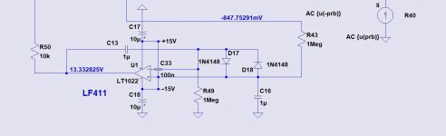
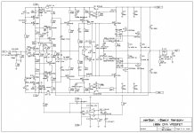
I may be wrong but I believe there is an error in this asc from your post #775 200W MOSFET CFA amp. C33 which goes between the two 15v rails, appears to shorted to the + input of the LT1022.
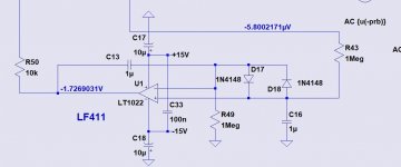
I had connected the cap like this in the modded version of the 100W CFA and could not adjust the DC offset after much poking around I realised what the problem was.
When I ran the sim with the input shorted and load open to check the bias and offset, I got -847.7544mV DC offset. Removing the short as per your 100W CFA attached allowed me to make/ test the adjustment.
As I say I may be wrong and will defer to your knowledge.
Attachments
-
 Shorted Cap at Servo.JPG58.2 KB · Views: 1,316
 -
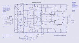 Shorted Cap at Servo Sch.JPG187.3 KB · Views: 1,248
 -
 Not Shorted Cap at Servo.JPG51.9 KB · Views: 1,292
 -
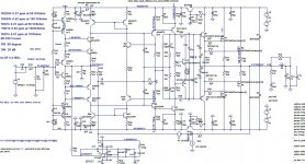 100 CFA- CM-VMOSFET-dado-1 Low PPM-sch.jpg208.7 KB · Views: 1,280
 -
200W-VMOSFET-efVAS-mc-RC-150-0_47u-OIC-DCservo- VDMOS ksubthres models-Vbe_blue.asc24 KB · Views: 379
Last edited:
No worries. If it wasn't for designers like you, I'd have nothing to build in the first place.
Because of my illness I haven't been able to start building this amplifier. I was hopeful to be well enough but it doesn't look like I will be able to enjoy this project. My hands shake too much. With that being said I am looking for a builder.
Last edited:
Hi, happy new year everyone 
By accident I stumbled accross a "funny" stability issue using different well known mosfet models.
I created a new thread to not highjack this one or turn it into a model discussion.
Simulation stability with different models - Dado's 200W CFA
Regards
Jørgen
By accident I stumbled accross a "funny" stability issue using different well known mosfet models.
I created a new thread to not highjack this one or turn it into a model discussion.
Simulation stability with different models - Dado's 200W CFA
Regards
Jørgen
I would like to offer gerbers for my 100W CFA and corresponding Power Supply.
I hope more people will build this amp.😉
I hope more people will build this amp.😉
Attachments
Probably, but first I would like to see if any interest to build 100W version. 😉and whether you will also share up to 200W MOSFET CFA gerbers
Hi Damir,
The 100W circuit uses BC550 and BC560 transistors. The BC560 is not easily available/obsolete now.
Looking at the specs, would the use of BC549 and BC559 be ok. The BC549/BC559 has a Vceo = 30V, as compared to the BC560 Vceo = 45V.
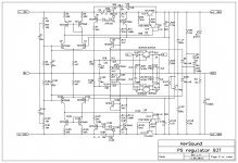
I notice there is a 15V zener diode limiting the rail voltage where the BC550/BC560 transisors are used.
My thinking the BC549/BC559 pairing should be ok in the transistor positions of Q15/Q17, Q11/Q12, Q16/Q19 and Q3/Q4.
This would allow the use of the lower noise BC549/BC559 transistors, similar to the BC550/BC560.
kind regards
steve
The 100W circuit uses BC550 and BC560 transistors. The BC560 is not easily available/obsolete now.
Looking at the specs, would the use of BC549 and BC559 be ok. The BC549/BC559 has a Vceo = 30V, as compared to the BC560 Vceo = 45V.
I notice there is a 15V zener diode limiting the rail voltage where the BC550/BC560 transisors are used.
My thinking the BC549/BC559 pairing should be ok in the transistor positions of Q15/Q17, Q11/Q12, Q16/Q19 and Q3/Q4.
This would allow the use of the lower noise BC549/BC559 transistors, similar to the BC550/BC560.
kind regards
steve
Last edited:
Hi Steve,Hi Damir,
2SC2240/2SA970, may these be replaced with KSC1845FA/KSA992FA
Kind regards
steve
Yes. 😉
Hi Damir,
Thanks for the quick reply.
Was I also correct with the substitution of BC549/BC559?
Thanks for the quick reply.
Was I also correct with the substitution of BC549/BC559?
Yes, instead of BC550C/560CHi Damir,
Thanks for the quick reply.
Was I also correct with the substitution of BC549/BC559?
I have a bunch of bc550/560bta transistors.Hi Damir,
The 100W circuit uses BC550 and BC560 transistors. The BC560 is not easily available/obsolete now.
Looking at the specs, would the use of BC549 and BC559 be ok. The BC549/BC559 has a Vceo = 30V, as compared to the BC560 Vceo = 45V.
I notice there is a 15V zener diode limiting the rail voltage where the BC550/BC560 transisors are used.
My thinking the BC549/BC559 pairing should be ok in the transistor positions of Q15/Q17, Q11/Q12, Q16/Q19 and Q3/Q4.
This would allow the use of the lower noise BC549/BC559 transistors, similar to the BC550/BC560.
kind regards
steve
https://www.diyaudio.com/community/threads/some-components-for-sale.314633/
It’s hard to resist such a good offer. I just ordered pcb and plan to build it along side Astx’s amp.Any fruits born from offered gerbers? 😉
Good, show your progress here.It’s hard to resist such a good offer. I just ordered pcb and plan to build it along side Astx’s amp.
Thank you very much!I would like to offer gerbers for my 100W CFA and corresponding Power Supply.
I hope more people will build this amp.😉
- Home
- Amplifiers
- Solid State
- 200W MOSFET CFA amp