Eric,Steve,
Here's the response of the cf/balsa, at 1 meter on axis. This is in a frame with with foam around most of the perimeter (not the corners) and a Dayton DAEX25FHE-4 exciter at about the .45/.45 location. Frankly it's pretty similar in overall character to my plywood panel of the same dimensions, but 6 dB louder.
Eric
...hmm... would you share also plywood? ;-) perhaps already done somewhere before...
Why I ask : it is because after the "FR reading training" I had with Steve in the previous posts, it seems, as you mentioned, the panels have characteristics independent of the membrane material (certainly in dome limits).
The remarkable points in common between your panel and other FR we shared are the peaks in the medium to high frequencies, the slow slope starting at some kHz, the peak above 10k.
What is not in your FR is a large hole in the 100/300Hz.
Do you have the intention/possibility to make outdoor measurements (or other solution...) to sort what is from the panel (in all its components : membrane, frame, exciter...) and from the environment (walls...)? When I did those outdoor measurements with my plywood panel, I was afraid by the level generated at 2k by the spine on the rear side and from the canvas, I understood I was wrong thinking peaks in the medium were from the boundaries.
Christian
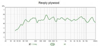
Here's the plywood. Same size panels as the carbon (406 mm x 584 mm), and same foam perimeter mounting. And with the same dayton exciter, except using two exciters instead of just one....hmm... would you share also plywood? ;-) perhaps already done somewhere before...
Eric
Attachments
Christian.
it's not so much about using mass to try and damp the peak that usually appears above the 9k point.
it's more to do with preventing the cancellations and peaks within the coil area.
If you can imagine an old cart wheel with its spokes joining the outer rim with the centre shaft.
If you try to imagine the rim of the wheel being the exciter coil foot.
Now imagine the high frequencies being fired into the centre , like the spokes of the wheel , all meeting in the centre (colliding).
The hf is trying to reach the other side of the coil foot, hopefully you can imagine what kind of mess this would make in the coil foot area ?
Breaking up these inward firing waves is , to me , is very important.
There are various ways to do this,heavy mass is one way of course, but I too dislike the sound this method produces.
I treat heavy panels differently to light panels ,like ply and eps .
If you touch a eps panel with a finger , you can change the sound considerably.
If you touched a ply panel with your finger it would make very little difference.
Things I do to ply to improve the sound , I would never do to an eps panel.
This is why, in the past I have called them a different bread !
Regarding the suck outs in the 100hz to 300hz area, on ply panels , have you tried sliding a small weight around the panel ,while playing pink noise ,and watching the plot change in real time.
Using this method you can fill in and extend the low end response.
When and if you find a good point which reduces the such out , you place a weight in that position.
Once this is done , you can ,if more is needed start again and place another weight in another position on the panel.
I think I had about 4 AA batteries stuck on my 3 foot x 2ft ply panel with blu-tack , that is until one tell off .
I actually used the AA batteries to slide around the panel and just stuck them in place , you can see them in the pictures on the dml for pro use forum.
If you don't like the sound ,they are easy to remove, if you like the sound you can glue them in the same position on the back of the panel.
Steve.
Thanks Eric.
did you happen to take any plots of the c.f. Panel freely supported with no edge damping ?
just for reference to see if there is any similarities with other thin panels or heavier panels for that matter.
does the hf hold up all the way to the edges or are they restricted to a central area ?
I'm still thinking of applying epoxy to my second panel for comparisons ,not sure if it is necessary to use a fibre glass matting ,but it would be interesting ?
I did look on line ,but wasn't sure.
Not sure they use the same terminology over here for types of fibre glass, if you don't know what you are doing when ordering ,your stuck with the wrong grade .
Steve.
@spedge , @Veleric ,Hello Steve,
....
On my side, I think to get basic figures from cardboard (stiffness, aerial mass) to bring it in the scope.
Christian
To place the cardboard in the "material graph", I made some evaluations.
My piece of cardboard is 48cm x 77cm, 1ply, 2mm thick, about 6mm as fluting space, for 157g.... so seems thicker the last one you are testing Steve
I find :
mu = 0,42kg/m²
D = 2Nm (estimation with the cantilever beam method see #4185)
fc = 8400Hz
D/mu³ = 27
Some findings about cardboard vocabulary
Is your cardboard single wall board F flute and mine E flute?
Steve,Christian.
are the speaker measurements you were talking about , the klippel system ?
I believe audio science review forum are now using this method to review and measure speakers.
Steve.
You will find in the attached document (from my notes) links to documents and video about MMM (Moving Microphone Measurement). It is an interesting simple method to get quickly a measure averaged over the listening area. The limitation is that there is no time aspect... I would agree on the fact that so many things happen without delay so this kind of method cover almost all the needs.
Christian
Attachments
Thank you EricHere's the plywood. Same size panels as the carbon (406 mm x 584 mm), and same foam perimeter mounting. And with the same dayton exciter, except using two exciters instead of just one.
Eric
The difference 1 or 2 exciters makes perhaps the comparison difficult.
At least all have in common the peak above 10k
Christian
Eric.
i was also going to ask, on the ply panel, did you place the microphone in between the two exciters or in front of one of the exciters ?
i only ask ,as there will be cancelations between the two exciters and across the panel surface and peaks of course.
this is one of the reasons i never use two exciters on one panel.
steve.
Christian.
I'm sorry, I forgot to say thanks for the video of the moving microphone .
interesting idea of moving the microphone around in a swirling motion, not just side to side and up and down.
although I'm not sure that moving the microphone back and forth closer to the speakers is a good idea as this will be like turning the volume up and down ?
There were a few other things I was having trouble with especially when using this method for room dsp setup on ordinary speakers let alone dml.
In my room at the moment I don't have a lot of room, so using that method would put the microphone a little too close to objects in my room, let alone getting very close to a mixing console .
I could go on but that's a different topic.
Steve.
Thanks Steve. I was thinking of a canvas panel with the central small piece of thin wood, which I think would help keep the voice coil parallel in the gap. I had the same concern with what I did with the XPS, which is why I kept the support arms equal lengths, to evenly load the voice coil. I remember reading about a commercial speaker company working on applying voice coil drive to a mylar membrane. They couldn't keep the voice coil in the gap, and eventually gave up!Bdjohns.
when you mentioned a spiderless canvas panel , I suddenly thought ,why didn't I think of that !
But then thinking about it , looking at your coil former ,I started to think, what if there was some canvas wobble going on .
There is nothing keeping the coil centrally in the grooves, you could get some rubbing and buzzing ?
I'm not saying it isn't possible but it's something to think about.
or make a minimalist spider that makes very little noise.
Steve.
Bruce
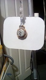
I took a photo of the panel with rounded corners (I'm not sure this made any difference to the sound)and the blu-tack blob.
I then in the third photo made a very very small blob.
I halved the size and then halved the size again.
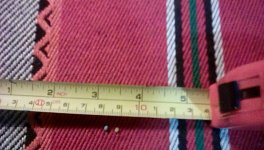
In the fourth photo is the very small blu-tack blob with an uncooked couscous , I have no way of measuring the weight of these as they are so small.
But as can be seen in the fifth photo ,the affect of the miniscule piece of blu-tack on the response is pretty much the same.
Pretty flat above 2k.
This was at about 30cm.
Steve.
I then in the third photo made a very very small blob.
I halved the size and then halved the size again.
In the fourth photo is the very small blu-tack blob with an uncooked couscous , I have no way of measuring the weight of these as they are so small.
But as can be seen in the fifth photo ,the affect of the miniscule piece of blu-tack on the response is pretty much the same.
Pretty flat above 2k.
This was at about 30cm.
Steve.
Attachments


Good point. Any ideas for concepts? I don't really have any idea what to try.With CNC, there is no reason the panel has to be uniform. Just food for thought.
Eric
https://www.tectonicaudiolabs.com/technology/
I notice in the animation of the cone on the left , the spider problems that can cause a lot of problems with dml also.
I don't know what the frequency the animation is showing.
The dml looks like it has 4 rigid mounting points, and probably some kind of foam or rubber on the edges?
they don't seem too worried about the hot spots in the corners ,or what looks like bottoming out on the foam on the short edges ?
they also use a little eq to smooth out the response .
they also have some dips and peaks above 10k ?
They were probably using too low a frequency to show the panel and cone movement ?
Steve.
No problem SteveChristian.
I'm sorry, I forgot to say thanks for the video of the moving microphone .
interesting idea of moving the microphone around in a swirling motion, not just side to side and up and down.
although I'm not sure that moving the microphone back and forth closer to the speakers is a good idea as this will be like turning the volume up and down ?
There were a few other things I was having trouble with especially when using this method for room dsp setup on ordinary speakers let alone dml.
In my room at the moment I don't have a lot of room, so using that method would put the microphone a little too close to objects in my room, let alone getting very close to a mixing console .
I could go on but that's a different topic.
Steve.
It seems the method comes from acoustical engineer in almost empty room or theater. I have the same concern not to come to close to object and also not too much back to front to avoid important level change.
Christian
Have you ever tried to make a hole in the center? After all, a hole can be of different sizes and shapes, with edge damping...Now imagine the high frequencies being fired into the centre , like the spokes of the wheel , all meeting in the centre (colliding).
The hf is trying to reach the other side of the coil foot, hopefully you can imagine what kind of mess this would make in the coil foot area ?
Breaking up these inward firing waves is , to me , is very important.
For sure you can say "pretty flat" Steve. Unusually flat even!I took a photo of the panel with rounded corners (I'm not sure this made any difference to the sound)and the blu-tack blob.
I then in the third photo made a very very small blob.
I halved the size and then halved the size again.
In the fourth photo is the very small blu-tack blob with an uncooked couscous , I have no way of measuring the weight of these as they are so small.
But as can be seen in the fifth photo ,the affect of the miniscule piece of blu-tack on the response is pretty much the same.
Pretty flat above 2k.
This was at about 30cm.
Steve.
A piece of 8x12x3.5mm of a similar gum is around 0.85g so about 2.5mg/mm³. Let us assume a 2.5mm diameter blob so about 8mm³ given about 20mg. Let us say the cardboard is 0.350kg/m² or 0.35mg/mm². The 25mm disk of cardboard in the voice coil area is 490mm² so 170mg. The blob mass is 10% of the disk mass. A new rule of design???? If somebody could check...
Christian
Stevehttps://www.tectonicaudiolabs.com/technology/
I notice in the animation of the cone on the left , the spider problems that can cause a lot of problems with dml also.
I don't know what the frequency the animation is showing.
The dml looks like it has 4 rigid mounting points, and probably some kind of foam or rubber on the edges?
they don't seem too worried about the hot spots in the corners ,or what looks like bottoming out on the foam on the short edges ?
they also use a little eq to smooth out the response .
they also have some dips and peaks above 10k ?
They were probably using too low a frequency to show the panel and cone movement ?
Steve.
From all the views I have in mind of Tectonic DML (simulation or drawing or picture), it seems they have a suspension method by only those 4 points. I have something about that in my notes I will search later.
Their FR are presented with EQ. I don't remember an FR without.
- Home
- Loudspeakers
- Full Range
- A Study of DMLs as a Full Range Speaker