Hi all
I'm struggling getting the parts together here in the UK.
The caps and inductors in stock DigiKey but not Mouser
The current sense in stock Mouser but cannot find at Digikey
I'm also after some other components that are in stock at Mouser but not Digikey
Are there any alternatives to Kennet/Nichicon caps and bournes inductors so I can get 1 order at 1 place and avoid £24 delivery fees?
I ordered parts recently also. The Kemet cap was out of stock at both Digikey and Mouser here state side. I ended up ordering these caps instead. Spec wise they are close with an ESR a hair lower but they are longer.
https://www.mouser.com/ProductDetail/661-EKYB500E471MJ30S
https://www.mouser.com/ProductDetail/661-EKYB500E471MJ30S
The entire world is experiencing a severe shortage of electronic components. It's not just us DIYers. Mercedes and Apple and IBM can't get the parts they want, either.
One pragmatic way to approach this is: choose and build TWO projects simultaneously. Order all parts for both projects simultaneously. The ones that DigiKey has in stock, you buy from DigiKey. The ones that Mouser has in stock, you buy from Mouser. Yes, that's two orders and two £24 delivery fees. But it's also two projects! Honor has been preserved; there was no profligate waste of money, no careless squandering of precious resources. One order per project, as it always has been.
One pragmatic way to approach this is: choose and build TWO projects simultaneously. Order all parts for both projects simultaneously. The ones that DigiKey has in stock, you buy from DigiKey. The ones that Mouser has in stock, you buy from Mouser. Yes, that's two orders and two £24 delivery fees. But it's also two projects! Honor has been preserved; there was no profligate waste of money, no careless squandering of precious resources. One order per project, as it always has been.

I thought I had found the inductors however they are listed as 4.5a, there are these available, also bournes.
Can they work?
2.2µH Unshielded Wirewound Inductor 6.5A 21mOhm Max
Can they work?
2.2µH Unshielded Wirewound Inductor 6.5A 21mOhm Max
1. Check post#1 of this thread to learn the physical size of the inductor which the PCB is designed for. Lead spacing and body diameter. Check whether your proposed replacement inductor has the same lead spacing and the same (or smaller) body diameter.
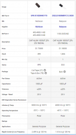
2. Use the comparison feature of DigiKey's website to get a side by side table of the specifications of the original, and the proposed replacement, inductor. Check to see whether the replacement is as good or better in every case. Here's an example, using DigiKey's site to compare two capacitors.
_
2. Use the comparison feature of DigiKey's website to get a side by side table of the specifications of the original, and the proposed replacement, inductor. Check to see whether the replacement is as good or better in every case. Here's an example, using DigiKey's site to compare two capacitors.
_
Attachments
Hi Mark
Thank you for your reply.
I played around with the find similar on mouser for hrs today.
Not having a clue what I'm doing (and slightly impatient) I aimed for parameters as close as possible to your original specs
I've found the following in stock
Wurth Fixed Inductors WE-TI RadXtnd Ld605 WW2.2uH 6.3A .01Ohm srf 65Mhz and
Panasonic FM-A Series caps 50v 470uf ripple 2260 whilst I can't find exact esr numbers they are listed as ultra low esr (down to 12mOhm)
I'll be using a prototyping pcb so component size doesn't matter.
The only way I'll know if the parts work is listening so fingers crossed
Hi all, in trying to find replacement caps for Marks awesome little filter I've been on what I hope is a learning curve.
I'm starting from absolute zero knowledge so please bear that in mind.
Please let me know if I'm on the right track albeit at a very basic level.
A basic smps despite on board rectification will still output DC with ripple (noise) caused by the switching mechanism, passing some ac or both? The filter uses inductors and caps to smooth out the ripple.
ESR is the resistance of DC current so the lower the number the better, as a side shoot lower ESR also reduces power loss from internal heating and extends the life of the capacitor.
The high no for ripple is the caps ability to withstand ripple currents before excessive internal heating occurs?
When looking at data sheets ESR appears to not be mentioned but impedance is. when looking at the sheet we can use impedance as an estimate of ESR for the given frequency as at lower frequencies they are pretty much the same only diverging at higher freq.
Err, I am not sure I am following you, nor where to start...
FOR THIS PROJECT, AND ALL IMHO, not having designed this filter.... you should seek for caps that have a low impedance at high frequencies (read at hundreds of kHz). For example a given low ESR at say 100kHz (or higher, just as an example), as that will help filtering out the HF garbage inherently produced by the SMPS (as if the ESR will be of course good at lower frequencies then, if needed).
DC is what you want at the output, ripple (and other bits due to response to regulation) can be treated elsewhere after the filter if really needed but a simple way to address it is to start with is a good SMPS, yes SMPS passes on some (IMHO quite negligeable for our audio purposes vs other solutions) 100/120Hz residues and possibly multiples of it at even lower magnitudes, but more over SMPS produces really quite a bit of garbage at its switching frequency (and multiples), say depending on SMPS units anything between 40kHz to 300kHz, and finaly some garbage in the MHz range.
The filter is there to get rid of the last two, especialy efficient on the first one I would say, and while at it it can possibly be welcome as small energy reserve due to the caps and ripple reduction depending on the following stage (what you plug behind, that's very unit dependant), but I see that as a small potential side effect.
Bottom line for your cap choice:
All IMHO and not sure I made it more clear LOL
Claude
FOR THIS PROJECT, AND ALL IMHO, not having designed this filter.... you should seek for caps that have a low impedance at high frequencies (read at hundreds of kHz). For example a given low ESR at say 100kHz (or higher, just as an example), as that will help filtering out the HF garbage inherently produced by the SMPS (as if the ESR will be of course good at lower frequencies then, if needed).
DC is what you want at the output, ripple (and other bits due to response to regulation) can be treated elsewhere after the filter if really needed but a simple way to address it is to start with is a good SMPS, yes SMPS passes on some (IMHO quite negligeable for our audio purposes vs other solutions) 100/120Hz residues and possibly multiples of it at even lower magnitudes, but more over SMPS produces really quite a bit of garbage at its switching frequency (and multiples), say depending on SMPS units anything between 40kHz to 300kHz, and finaly some garbage in the MHz range.
The filter is there to get rid of the last two, especialy efficient on the first one I would say, and while at it it can possibly be welcome as small energy reserve due to the caps and ripple reduction depending on the following stage (what you plug behind, that's very unit dependant), but I see that as a small potential side effect.
Bottom line for your cap choice:
- cap's ripple value probably not key in this application (some is seen at start up, but well)
- ESR at high frequency is a key parameter, the one to look at
All IMHO and not sure I made it more clear LOL
Claude
It's a DC power supply. We want pure, zero Hertz, DC on the output. We don't want any other frequencies. They are all undesirable, they are all "noise", and we want to remove them.
In power supply filters, ESR/impedance is undesirable because it gets in the way, preventing the capacitors from shunting high frequencies (noise!) to ground. Low ESR is good, it means more noise gets sent to ground and less noise gets sent to the your audio equipment at the filter output. High ESR is bad, it means more noise gets sent to your gear.
After measuring a lot of capacitors for ESR, I've concluded that large values of ripple current rating usually go hand-in-hand with tiny values of measured ESR. Which is nice because there are a lot of electrolytic capacitors whose datasheets do include ripple current rating, but don't include ESR. Therefore: When ESR data is scarce, sort by ripple current rating. Find the in-stock capacitor with the highest rated ripple current. Compare that ripple current against the ripple current rating of a Panasonic FOX ROMEO ("FR") capacitor of the same physical size, same voltage rating, same capacitance. [the Panasonic FR is probably not in stock because people like me bought all of them.] If the in-stock cap you found, has a higher ripple current rating than the comparable Panasonic FOX ROMEO, use that cap and be happy.
Some datasheets prefer to use the word "impedance" rather than "ESR", but for the purpose of choosing capacitors for this particular PCB {and no other}, you can assume the two words mean approximately the same identical concept.
If the in-stock cap you found does have an impedance rating or an ESR rating, and if that rating is lower than the comparable Panasonic FOX ROMEO, use it and be happy. Be sure to compare numbers in the same column of the table; sometimes they tabulate at more than one frequency. So compare apples to apples by staying in the same column and comparing at the same frequency.
Summary: find electrolytic capacitors that are better than Panasonic FOX ROMEO electrolytic capacitors. "Better" means either lower ESR/lower impedance, or else higher ripple current rating. Perhaps both! If no such capacitors are in stock, pick the best one that is in stock, and realize that your filter performance won't be as good. Later, when better capacitors become available in-stock again, you can remove the low performers and replace them with high performers.
Last edited:
Thank you for the replies
It seems I concluded the right approach but maybe without the correct reasoning.
The caps I ordered are identical to the FR range with exception of lifespan.
The FR range seem to be exceptional in that area.
May I ask a word of advice?
I intend to crack open the wall wart to replace the extremely thin and far too long wire.
It currently has a ferrite, I'm sure I read somewhere ferrets are not really required and can be detrimental
Should I refit the bead?
Hi! Great! Any problems using solid polymer electros here for the 470uf? I've found some Nichicon with very good ESR (10mΩ@100kHz ). But I've never used this kind of caps them before so I'm not sure if there's any problem using them.
I'm using this little circuit between a DC - DC converter and a LDO. Like this:
DC - DC converter --> SMPS --> LDO
Cheers!
I'm using this little circuit between a DC - DC converter and a LDO. Like this:
DC - DC converter --> SMPS --> LDO
Cheers!
Still watching & waiting for these kits in the DIY Store. Any idea when they will be available?Quote:
"I'll be ordering the parts to restock the kit in the store this week"
Please advise when the kits are available for purchase again. Thanks
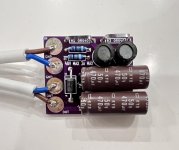
So after weeks of finding components, cables, pcbs, box etc I finally made the filter.
Cracked open the wall wart to replace the cable only to find its only a step down transformer. Its bloody 12v ac
If only I had actually looked at the day rear panel

To rub salt in the wound the power supply caps I ordered are too big so basically a few lessons learnt
Cracked open the wall wart to replace the cable only to find its only a step down transformer. Its bloody 12v ac
If only I had actually looked at the day rear panel
To rub salt in the wound the power supply caps I ordered are too big so basically a few lessons learnt
I followed the other thread separately, but...
Having built a dozen (or was it more?) of these filters, using them in many various occasions and with sometimes odd set ups, I can only say that once I respected their scope they NEVER brought any negative, whereas on most occasions they brought a lot of positive! As stated in the past, we are speaking line amps , power amps (both Class A and Class D), HP amps, DACs and so many other more or less audio related devices I have loss count for.
Following Mark's device, I always have a few spares with me, enough to try at friends in potential daisy chain configuration and I, on current over-rated devices, even dared out slightly out of scope uses (not recommended unless you know exactly what you do!). Just for me to have a feel of potential tweaks... either around a single or a combination of these excellent filters, or around similar filters clearly inspired by these when completely out of these filters's scope.
Highly recommended... as Stererophile would say when they really mean it, coming across a better component...
Claude
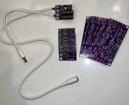
So, pcb ordering was successful and while I was at it I ordered Quasimodo boards also. I have officially built my first diyAudio project! Great first project to work through ordering boards and parts from Mouser/Digikey, not to mention have to use the filter to find substitution parts. This was the first thing I had soldered since playing with RC cars 30 years ago. With all the tips, tricks, instructions, and excellent solder from the diyAudio store it was a piece of cake. Didn’t quite read close enough ordering the DC extension cord, ordered a 2.1x5.5 instead of 2.5x5.5. Went back to look last night and Mark had said, couldn’t find any heavier gauge 2.5x5.5mm extension cables. So ordered a new jack mount for the ACA mini build this week in 2.1x5.5, the Meanwell 2.5x5.5 female makes good enough contact on the 2.1x5.5mm. I do have a non-Altoid case for it, but that will be revealed when the ACA mini is completed.Awesome. Will give that a try. Always learning, always learning.
Now to go back through the thread and see if I can measure the improvements with the oscilloscope. Thanks Mark for the project, and I think it should remain out of stock at the store to force Noobs to jump in and order our own boards.
Attachments
Of course you can measure it with a scope (and are unlikely to be disapointed)... and / or you could just listen to it, to find out if you hear any improvements and if so which ones 🙂
It is so easy to plug it in and out to listen to the difference...
Have fun and well done
Claude
It is so easy to plug it in and out to listen to the difference...
Have fun and well done
Claude
- Home
- Source & Line
- Analog Line Level
- PO89ZB, an inline DC filter for SMPS wall warts. Preamps, HPA, Korg NuTube, etc