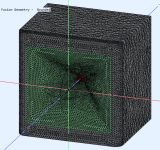
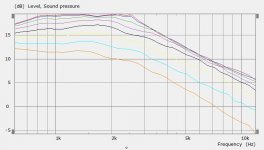
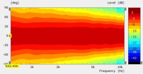
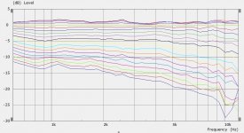
Thank you, Marcel, for this study because I think it proves the points that I made. 1) the differences would be minimal, and 2) there will be tradeoffs that different designers will choose between. For example, I prefer the enclosed waveguide because the DI is flatter and higher at LFs.BTW, this is an effect of an enclosure I repeatedly observe in the data - it's not helping the lower-end directivity. All it does is that it's actually a bit less controlled, compared to a "bare" free-standing waveguide (the DI is actually a bit lower below 1k when enclosed). This is without any additional flat baffle around the mouth, just a rear-side "housing" (all axisymmetric).
View attachment 1018927 View attachment 1018928 View attachment 1018929
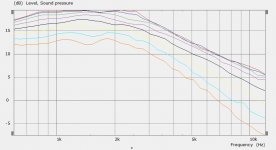
The corresponding results:
View attachment 1018930 View attachment 1018931 View attachment 1018932
Then there is the fact that one must consider the whole picture where the free-standing waveguide must be placed on the woofer box which will then diffract in a manner quite different from the enclosed waveguide. This may or may not be an advantage - most likely another tradeoff to be considered.
You always do, no matter what I post 🙂Thank you, Marcel, for this study because I think it proves the points that I made.
Is it? Strange, I read the data as quite the opposite.For example, I prefer the enclosed waveguide because the DI is flatter and higher at LFs.
- What is missing in that study is the front baffle - there's no flat panel around the mouth that would otherwise cause another sharply localized diffraction. I believe it would look considerably different if the enclosure was a box with a flat front panel. But fluid has obviously a lot more experience simulating this.
Last edited:
Has anyone tried running an Abec/Akabak simulation on a system with multiple sockets?
I tried to run the demo versions of Abec and Akabak on a Cisco server having 4 x 18 xeon E7-8880v3 cores, and both programs got stuck. Calculations start normally, but then get stuck at a certain point in time (the task manager shows that the calculation is performed normally, there are no "not responding" conditions, but calculations never reach 100%).
The second unpleasant point is that Abec/Akabak cannot work with Windows Processor groups. So Akabak/Abec sees only half of the physical cores if their number exceeds 64 cores.
How many elements did the simulation have? Sometimes if you go significantly above 10,000 elements ABEC will get stuck in a loop and spin it's wheels for many hours without finding a solution.I tried to run the demo versions of Abec and Akabak on a Cisco server having 4 x 18 xeon E7-8880v3 cores, and both programs got stuck. Calculations start normally, but then get stuck at a certain point in time (the task manager shows that the calculation is performed normally, there are no "not responding" conditions, but calculations never reach 100%).
That's what I wonder about the cirsym "baffle" how close is it to the full 3D rectangular sim. I will check to see what the difference is. It is a real pain to make a full size baffle going to half symmetry with a waveguide, for whatever reason 1/4 symmetry works significantly better and still lets you see the horizontal and top vertical responses well enough.- What is missing in that study is the front baffle - there's no flat panel around the mouth that would otherwise cause another sharply localized diffraction. I believe it would look considerably different if the enclosure was a box with a flat front panel. But fluid has obviously a lot more experience simulating this.
From what I have seen in simulation and anecdotal evidence from those who have measured them, the freestanding guide is much less affected by the woofer box than the baffled guide is to nearby solid objects. I see this as being it's greatest potential advantage. Hard to say if it would make any audible benefit.Then there is the fact that one must consider the whole picture where the free-standing waveguide must be placed on the woofer box which will then diffract in a manner quite different from the enclosed waveguide. This may or may not be an advantage - most likely another tradeoff to be considered.
MarcelYou always do, no matter what I post 🙂
That's not true at all. I almost always agree with you. It's just that I am far more likely to post when I disagree.
From what I have seen in simulation and anecdotal evidence from those who have measured them, the freestanding guide is much less affected by the woofer box than the baffled guide is to nearby solid objects. I see this as being it's greatest potential advantage. Hard to say if it would make any audible benefit.
That would be a great advantage if it's true. It just isn't obvious to me why it would be.
Again, these are very small effects in the bigger picture.
Marcel
That's not true at all. I almost always agree with you. It's just that I am far more likely to post when I disagree.
Dear Sir, may i same to you, sincerely 🙂
From what I can gather the freespace termination seems to work both ways, it stops things coming in to mess up the pattern as well as it smooths them going out. Beyond seeing the effect I'm getting out of my depth very quickly on the why 🙂That would be a great advantage if it's true. It just isn't obvious to me why it would be.
Again, these are very small effects in the bigger picture.
For sure there is no way to know how much value to put on it in overall terms but maybe with enough incremental improvements it tips the scales to being beneficial.
How many elements did the simulation have? Sometimes if you go significantly above 10,000 elements ABEC will get stuck in a loop and spin it's wheels for many hours without finding a solution.
Probably you mean the singularity problem. But it is not my case I assume. I get stuck even at 2500 elements. With my laptop (HP 8470w) I don't have this problem with the same mesh. But with multi-socket server ABEC/Akabak behaves very strangely. 662 elements problem is solved completely (within 8 second). But even 2800 elements model get stuck Moreover, the more cores are activated in ABEC/Akabak's properties , the later the solver get stuck (with 64 active core the solver get stuck at 50%, with 24 cores at 20%, with 16 cores at 15%, etc). If anyone has access It would be interesting to see behavior of ABEC3/Akabak on other servers having 2 or 4 physical CPU.
 .
.No I haven't. Is there something about that shape that interests you?@fluid, ever tried a termination like this?
Here's the "baffle issue" - I've cut the curve at the apex and inserted 2" of a flat baffle. As a result there are now two sharply localized sources of diffraction - the edges of the flat segment. Of course in a rectangular box in won't be as bad as the distances to the outer edge will vary but this is the principle.


Last edited:
Original vs modified as shown -wesayso said:ever tried a termination like this?
BTW, you can easily switch between those charts by clicking on one of them and then pressing the left/right arrow keys.
Last edited:
That shows why I worry that it will be difficult to use circsym models to properly explore as a circular baffle of any flat area is bad.Here's the "baffle issue" - I've cut the curve at the apex and inserted 2" of a flat baffle. As a result there are now two sharply localized sources of diffraction - the edges of the flat segment. Of course in a rectangular box in won't be as bad as the distances to the outer edge will vary but this is the principle.
This is what I simulated and the diagonal is almost the same as the horizontal and vertical. There is as little flat baffle as possible and every edge and corner rounded.
Thanks, I like itNow, this is nice!
I don't agree because here is a rectangular guide that looks nearly as good, this was the one I thought I would build before more ideas took over. I still think it has a lot of visual appeal.It will suffer from the same limitations, the baffle diffraction should be accounted for.
Attachments
Is that Tritonia based?
Rectangular mouth has the obvious advantage of varying the distance even of the first baffe edge and further minimizing the flat areas. That's why I said I would opt for a rectangular as a baffled waveguide. Well, it has some other weaknesses, maybe not that important.
- Anyway, compared to a big free-standing round waveguide, it seems a little bit too complicated and in fact also compromised to me now.
Last edited:

- Home
- Loudspeakers
- Multi-Way
- Acoustic Horn Design – The Easy Way (Ath4)