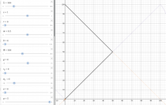
With a parametric equation there is yet another way to adjust a waveguide shape without changing its depth. Some kind of "3D profile rotation":
- variable h = 1.05
- (X(ht),Y((2-h)t)
https://www.desmos.com/calculator/q6p0phoeix (variable h is defined at the end of the sheet)
- variable h = 1.05
- (X(ht),Y((2-h)t)
https://www.desmos.com/calculator/q6p0phoeix (variable h is defined at the end of the sheet)
Now here is my conjecture -
If you took the below shown axisymmetric waveguide profile and placed it in a flat baffle of an enclosure (in such a way that the baffle round over would match the contour in the cross section), it would perform worse than the corresponding axisymmetric waveguide free-standing.

If you took the below shown axisymmetric waveguide profile and placed it in a flat baffle of an enclosure (in such a way that the baffle round over would match the contour in the cross section), it would perform worse than the corresponding axisymmetric waveguide free-standing.
BTW, with this setting of the parameters, the contour is still a simple pure OS - a useful sanity check.

- So someone with the access could put this formula into COMSOL optimization loop and find the best termination for an OS waveguide. (We probably wound't be very surprised but it would be nice to have it confirmed. I claim it can't be very different from the CE series - for a 1" throat, that is. For bigger throats it should be done differently, IMO.)
- So someone with the access could put this formula into COMSOL optimization loop and find the best termination for an OS waveguide. (We probably wound't be very surprised but it would be nice to have it confirmed. I claim it can't be very different from the CE series - for a 1" throat, that is. For bigger throats it should be done differently, IMO.)
Last edited:
Duct modes driving
This is perhaps for someone feeling enough interested in the matter - there remains an undocumented Ath feature that allows you to use (axisymmetric) duct modes as the driving, instead of a flat or spherical wave:
Source.Contours = ::duct 0,0,1
The three numbers are the weights of the (0,0), (0,1) and (0,2) modes (+/-). This way you can simulate a waveguide performance when driven by such wavefront (as has been done in this thread).
Thanks for the mention!Two examples of speakers using "this horn":
https://www.diyaudio.com/community/threads/hf10ak-12p80nd-custom-wg.360973/https://www.diyaudio.com/community/...-design-the-practical-way.354772/post-6214298
This shape was designed with ATH4 4.6
Last edited:
I got the bridge between Ath and MMM_toobox up and running, the speed is about 550ms per iteration after optimizing the simulation parameters but the parallel computing is not stable. Ath is getting hammered so sometimes hangs.
I'll try to decrease the pool size to see if there is a better setting or add a pause after Ath execution.
Under Matlab to give you more info WRT speed, Win10 AMD 5950x (16 cores/32 threads) = 2.25min total ram <32Gb (was 11.5min on my 4 core Mac) so about 80ms per iteration on average for Matlab native OSSE function.
BTW the Rot parameter makes the optimization tricky as it can make the profile curve back which does not work with MMM_Toolbox.
I devised a crude way around but if anyone has suggestion, I am all ears...
I don't see why you need Ath in the loop in the first place. For an infinite baffle simulation you can generate the waveguide contour directly in Matlab as the formula is readily available.
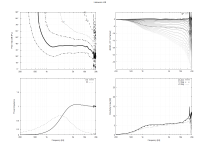
A revisit of Limacon v39 with Ath 4.8 and the reporting feature. Please see attached Mesh and ABEC settings used to generate the gnuplot.
Limacon v39
Superformula based waveguide with a 10.5deg exit to match the HF10AK.
380 x 280 x 114mm (Term.q = 0.995)
Limacon v39
Superformula based waveguide with a 10.5deg exit to match the HF10AK.
380 x 280 x 114mm (Term.q = 0.995)
Code:
Mesh.AngularSegments = 120
Mesh.LengthSegments = 20
Mesh.CornerSegments = 6
Mesh.ThroatResolution = 2.0 ; [mm]
Mesh.InterfaceResolution = 7.0 ; [mm]
Mesh.InterfaceOffset = 5.0 ; [mm]
ABEC.SimType = 1 ; infinite baffle
ABEC.Abscissa = 2 ; 1=log | 2=linear
ABEC.f1 = 200
ABEC.f2 = 20000
ABEC.MeshFrequency = 1000
ABEC.NumFrequencies = 100
ABEC.Polars:SPL = {
  MapAngleRange = 0,90,19
  NormAngle = 10    ; [deg]
  Offset = 115       ; [mm]
}
Report = {
  Title = "Limacon v39"
  Width = 1600
  Height = 1200
  NormAngle = 10
}
Attachments
Last edited:
x(t), y(t) projection visualization (try the "h" slider): https://www.desmos.com/calculator/t4wibyqzeu

Finally, I've revised the inputs. Now it's much more intuitive and stable - the basic parameters are the outer waveguide radius and nominal coverage angle. Also the 'bending factor' is now relative to a full round over (0 - 1.0), as the absolute value was very sensitive to other values.
https://www.desmos.com/calculator/1awn6hsodn
https://www.desmos.com/calculator/1awn6hsodn
Fascinating. If one now could see in real time the effect of the sliders in your standard report (e.g. 39-48.png above) it would be a fun excersie 🙂
//
//
Baffle mode - https://www.desmos.com/calculator/y47st9skiq
(There will be a step change in curvature where the WG connects the baffle. The OSSE formula is better in this regard.)

(There will be a step change in curvature where the WG connects the baffle. The OSSE formula is better in this regard.)
Last edited:
I think it's already possible with the MMM_toolbox, i.e. for an infinite baffle at least. That waits for someone with Matlab/Octave skills - I've never used that much.Fascinating. If one now could see in real time the effect of the sliders in your standard report (e.g. 39-48.png above) it would be a fun excersie 🙂
1) Glass of wine
2) An idea for a WG/CD behaviour
3) Move the "sliders"
4) Eyeballing graphs
5) One more glass
6) Heureka!
7) Push button "Order 2"
8) Sober
9) Hear postman knock on door
10) Hear Schostakovich 8th
//
2) An idea for a WG/CD behaviour
3) Move the "sliders"
4) Eyeballing graphs
5) One more glass
6) Heureka!
7) Push button "Order 2"
8) Sober
9) Hear postman knock on door
10) Hear Schostakovich 8th
//
I made an app using BabylonJS.
create the size of room
set speaker box size
set speaker box position within the room
set waveguide position on baffle
set waveguide params
substract the box and waveguide from the room to create the air space.
use HXT compiled with emscripten to create a fine tetrahedral mesh of the air / horn surface interface.
https://gitlab.onelab.info/gmsh/gmsh/-/tree/master/contrib/hxt
apply BabylonJS gpu physics to the tetrahedral mesh
assume box and waveguide are hard rigid surfaces
introduce a vibration on the mouth exit surface
watch the propagation of impulses in slow motion
I'm in the process of creating planes and surfaces to capture the polar data.
Realtime changes. 🙂
I hope to add the woofer cone position and shape too.
Last edited:
- Home
- Loudspeakers
- Multi-Way
- Acoustic Horn Design – The Easy Way (Ath4)