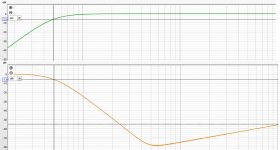
My "PassDIY 6-24XO" is set to 50Hz and LR24. Attached is the response measured with REW (using my laptop and an E-MU 0202 USB audio interface). This is the left channel, and the right is very similar (identical). The response of the low-pass section is rising above 5 - 600 Hz as can be seen. Using the 3.149 kHz testsignal (no50) from the Denon test-CD, I am able to hear a wek tone, presumably 3149. BTW the response bears some resemblance to the distortion plot for the LP filter as shown in Pa's article (page 5).
Attachments
If I feed a mono test signal to either channel, I am detecting a lot of crosstalk on both LXmini speakers when using the ACN. I use two monoblocks for the upper drivers, and a single stereo amp for the lower range drivers. If I bypass the ACN and run preamp direct to power amp, there is zero crosstalk. Therefore I am almost certain it is the ACN and not anything else in my system. Is this part of the design? The ACN is built according to the instructions, with no mods. Has anyone measured channel separation, or has anyone else experienced this?
Peace,
Tom E
Peace,
Tom E
Thanks so much, Nelson. I don't mean to take up your time, but something seems wrong. If it gets me any points, I purchased a beautiful new Threshold 400A at the time it was a new model and loved it until a local tech blew it up in the late 80's.Are you terminating the input of the undriven channel in a low impedance?
ACN: Both channel inputs were attached to preamp (output imp 50 ohms), all outputs attached to power amps (input imp 100k) when crosstalk detected. It is significantly loud. All voltages were near optimum before I put the ACN into the system, per instructions. Now I have it apart, all input and output leads disconnected from jacks. Using continuity probes, I find there is continuity between left and right channels, through both signal and ground. Of course, I understand the ground is common, but why the signal paths? I cannot see any faults in construction. Is this normal? Is there continuity between channels through the power supply filtering? Do I need to cobble a couple RCA jacks with resistors to test?
Regards,
Tom E
In my case the unused input was not terminated at all. My E-MU “sound card” might not be the best either. I shall try again shorting the unused input to ground. (BTW I run with an internal mains transformer and a LM317 based regulator.) Regarding the ca 3k tone I was referring to in the low pass part, in reality this will be attenuated also by my subwoofer system. So my crosstalk was between low and high, not between left and right.
More later…. And that you for the reply.
More later…. And that you for the reply.
Last edited:
Looking at the schematic it appears that the 6/18 setting on the second stage low pass filter just disconnects the feedback capacitor used for the 12/24 filters. This leaves both P1 and P2 along with their 10K resistors in series rather than bypassing P2 like the 6/18 setting does on high pass filter to bypass the second stage C. It appears that the resulting double resistor/pot series stage is used to compensate for the C/2 cap used in the corresponding second stage filter (2R*C/2 = R*C). This would allow the user to switch between 12/24 and 6/18 configurations without swapping out C/2 for C. Is this indeed the intent?
Hello All,
I have looked through several pages of this thread.
There does not seem to be any THD+N measurements or FFT's posted.
I did read some posts about hum and grounding.
Is this a just for fun DIY project?
I have looked through several pages of this thread.
There does not seem to be any THD+N measurements or FFT's posted.
I did read some posts about hum and grounding.
Is this a just for fun DIY project?
All of my projects are for fun, that's why I build them, it's my hobby. The preamp and 6-24 crossover are for my Lowther pm6a speakers and a VFET amplifier.
A fun project may perform poorly. If it makes a lot of noise and distortion I am less interested.All of my projects are for fun, that's why I build them, it's my hobby. The preamp and 6-24 crossover are for my Lowther pm6a speakers and a VFET amplifier.
Last edited:
Hello DualTriode,
it is always good to have a look at the distortion of an amp or an active crossover.
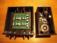
I have built two versions of the 6-24-active crossover from Nelson Pass. One for the Mid-High-crossover (2000-3000 Hz) and one for the sub
(60 - 120 Hz). I am really convinced from this active crossover. It is a possibility to build an active crossover to your specific needs at an affordable
price.
The active devices used in the buffers of the 6-24-ACO are J113 (Onsemi/Fairchild). Pretty cheap and more important at the moment - available!
If you are searching for lower distortion you could try other N-channel-JFets. You could exchange them with Toshiba 2SK170 or Linear Systems LSK170.
But you would have to adjust the constant current sources in each buffer cell to the demands of these different N-JFets on your own.
Toshiba and Linear System N-JFets are available in the diyAudioStore at fair prices. Most of the offers in the internet - especially the Toshiba 2SK170-
are fakes!
I have built my two 6-24-ACOs with the matched J113 delivered in the kit. These active crossovers sound great! But it always depends on the rest of
your setup. The chain is always as good as the worst link...
And this crossover is not a project with one standard recipe. You should have some knowledge about your drivers / speakerbuilding and you will have to know
where the crossoverpoints will be. You will have to experiment with simulators to get the right values for the caps and resistor values in the filters.
This crossover has no real equalization possibilities built in!
And a last sentence: I measure also distortion - but I also trust my ears. 🎼🎶
Cheers
Dirk
it is always good to have a look at the distortion of an amp or an active crossover.
I have built two versions of the 6-24-active crossover from Nelson Pass. One for the Mid-High-crossover (2000-3000 Hz) and one for the sub
(60 - 120 Hz). I am really convinced from this active crossover. It is a possibility to build an active crossover to your specific needs at an affordable
price.
The active devices used in the buffers of the 6-24-ACO are J113 (Onsemi/Fairchild). Pretty cheap and more important at the moment - available!
If you are searching for lower distortion you could try other N-channel-JFets. You could exchange them with Toshiba 2SK170 or Linear Systems LSK170.
But you would have to adjust the constant current sources in each buffer cell to the demands of these different N-JFets on your own.
Toshiba and Linear System N-JFets are available in the diyAudioStore at fair prices. Most of the offers in the internet - especially the Toshiba 2SK170-
are fakes!
I have built my two 6-24-ACOs with the matched J113 delivered in the kit. These active crossovers sound great! But it always depends on the rest of
your setup. The chain is always as good as the worst link...
And this crossover is not a project with one standard recipe. You should have some knowledge about your drivers / speakerbuilding and you will have to know
where the crossoverpoints will be. You will have to experiment with simulators to get the right values for the caps and resistor values in the filters.
This crossover has no real equalization possibilities built in!
And a last sentence: I measure also distortion - but I also trust my ears. 🎼🎶
Cheers
Dirk
Attachments
Matching is nice, but not crucial. It is convenient to consider 2SK170 / LSK170 in the
follower positions and continue to use J113 as constant current sources. This way
you spend half as much, buying only 1 quad of the XK170's and getting virtually the
same performance.
follower positions and continue to use J113 as constant current sources. This way
you spend half as much, buying only 1 quad of the XK170's and getting virtually the
same performance.
Hello DualTriode,
it is always good to have a look at the distortion of an amp or an active crossover.
I have built two versions of the 6-24-active crossover from Nelson Pass. One for the Mid-High-crossover (2000-3000 Hz) and one for the sub
(60 - 120 Hz). I am really convinced from this active crossover. It is a possibility to build an active crossover to your specific needs at an affordable
price.
The active devices used in the buffers of the 6-24-ACO are J113 (Onsemi/Fairchild). Pretty cheap and more important at the moment - available!
If you are searching for lower distortion you could try other N-channel-JFets. You could exchange them with Toshiba 2SK170 or Linear Systems LSK170.
But you would have to adjust the constant current sources in each buffer cell to the demands of these different N-JFets on your own.
Toshiba and Linear System N-JFets are available in the diyAudioStore at fair prices. Most of the offers in the internet - especially the Toshiba 2SK170-
are fakes!
I have built my two 6-24-ACOs with the matched J113 delivered in the kit. These active crossovers sound great! But it always depends on the rest of
your setup. The chain is always as good as the worst link...
And this crossover is not a project with one standard recipe. You should have some knowledge about your drivers / speakerbuilding and you will have to know
where the crossoverpoints will be. You will have to experiment with simulators to get the right values for the caps and resistor values in the filters.
This crossover has no real equalization possibilities built in!
And a last sentence: I measure also distortion - but I also trust my ears. 🎼🎶
Cheers
Dirk
Hello,
Bottom line, I do not want to hear noise or distortion.
To hear noise or distortion when the music is playing either or both will need to be pretty extreme. The program material does significant masking.
Noise is the worst. The program masks distortion and there is no distortion produced in the silence between the tracks.
Hum, buzz or hiss between the tracks is my pet peeve.
For high sensitivity Compression Driver wave-guide tweeters, with an active crossover I pad the tweeter amplifier output to operate at several watts. Picture the typical THD+N vs. power output plot. The THD+N (SINAD) improves drastically as the power output increases to 3, 4 or 5 watts.
My concern is how much noise does the J113 Jfet and bias resistor make?
Perhaps in this buffer / crossover circuit with little or no gain the noise will not be problematic?
I am thinking about purchasing one of the basic kits and installing some sockets to allow swapping out different Jfets and bias resistors to make some measurements.
Thanks DT
At 1v out it's something like -100 dB of each and that's on my noisy bench next to my solar invertter

I don't think you will find it very audible, but you can improve on that a bit with the LSK or Toshiba parts.
I don't think you will find it very audible, but you can improve on that a bit with the LSK or Toshiba parts.
Interesting idea as I still have a few Sk170s.
What about the bias resistors? Should they stay in place for the Sk170? I guess they are still needed to define the current for the J113.
DC offset? What would be the best idss for the Sk170?
And I think the pin out is different, so crossing some legs is required.
And btw, my build with J113 is dead silent with a good power supply on a 85db speaker - much less hiss than a Behringer CX (Ok, not a state of the art comparison) I tried before. If this is till true for a horn tweeter I don't know.
Last edited:
I can contribute in saying that the crossover was completely silent on my jbl 2450 compression drivers on Yuichi horns (somewhat 110db). I had to turn it down quite a lot with the trimpots to align with 97db 15 inch midwoofers.
The resistors on the j113 set the bias usually around 8 ma or so, otherwise bias tends to be high.
Output is cap coupled so offset is not an issue.
Output is cap coupled so offset is not an issue.
I can contribute in saying that the crossover was completely silent on my jbl 2450 compression drivers on Yuichi horns (somewhat 110db). I had to turn it down quite a lot with the trimpots to align with 97db 15 inch midwoofers.
Hello, Robin De Wolf,
Thank you for the reply.
I am doing similar but different. With JBL 2123 mids and JBL 2451 CD's (plus Rane AC23 crossover). At the output of the Crown amplifier there is a inline capacitor to protect the CD from DC and a hard wired L-Pad to attenuate hiss. This is not my idea I stole it from the JBL M2 manual.
Thanks DT
At 1v out it's something like -100 dB of each and that's on my noisy bench next to my solar invertter
I don't think you will find it very audible, but you can improve on that a bit with the LSK or Toshiba parts.
Thanks Nelson Pass,
You are a smart hands-on kind of guy, if you say so I have no reason to doubt.
If I want to own and understand something I build and test it on my bench. If I can see the noise profile and see the harmonics on the FFT I know what it is that I am hearing or not hearing.
Yesterday I ordered the PCB, J113’s, bias resistors plus 4 each matched 2SK170’s.
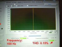
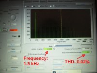
Coming up; Jfet curves, noise and distortion plots.
Thanks DT
On the bench
Keysight B2912A SMU
APx555
Sample J113 plots
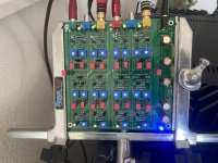
Surprisingly, I got it to work the first time. 6L6's build guide was super helpful and much appreciated. Also, I used Mr. Pass' recommendation (Post #230) to use Digikey part 116-87-210-41-006101, which made for easy swapping of the WIMA caps.
Does anyone have a .cad drawing of the backplate for the 2U galaxy 230x230mm chassis they be willing to share? I want something similar to the ACN backplate silkscreen, so can order a custom CNC'd backplate from the diyaudio store.
Thanks!
Does anyone have a .cad drawing of the backplate for the 2U galaxy 230x230mm chassis they be willing to share? I want something similar to the ACN backplate silkscreen, so can order a custom CNC'd backplate from the diyaudio store.
Thanks!
Attachments
- Home
- Amplifiers
- Pass Labs
- DIY biamp 6-24 crossover