In this case the DC load is across the two supplies, not to ground, so the two supplies should beThis is my first attempt at using a dual power supply. It seems to me that it solves some problems of having to acquire HV caps, etc.
Is it necessary to have the pos and neg legs be an exact mirror of the other? Can one leg be a pi filter and the other a choke filter? IF so, are there any advantages to doing it this way?
similarly configured. But instead you could connect this as a single supply, with two equal series capacitors,
and with an equalizing resistor across each cap.
DC drift is the enemy of direct coupled amplifiers. This can be partially fixed using a differential front end.
DC stabilized PSs are the normal in anything serious. And while using tubes the heater supplies were stabilized as well.
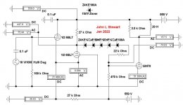
The five 100V Zener diodes provide level shifting to avoid signal loss between stages.
This schema is a first pass & is not optimized. 10V rms on the front end results in 7 Watts in a 3.5K load.
DC stabilized PSs are the normal in anything serious. And while using tubes the heater supplies were stabilized as well.
The five 100V Zener diodes provide level shifting to avoid signal loss between stages.
This schema is a first pass & is not optimized. 10V rms on the front end results in 7 Watts in a 3.5K load.
Attachments
Don't over-complicate. K.I.S.S. If you are not doing a direct-coupled (transformerless) output, tubes are far happier single-supply. (Maybe a minor negative supply for bias, but not a fork in the MAIN supply.) High voltage caps are readily available, at specialists and even at Mouser/Digikey/etc. You need some balancing resistors but you should have bleeder resistors anyway. Here is a well-tested plan from over 45 years ago (I didn't want to go too deep in the vault).Is it necessary to have the pos and neg legs be an exact mirror of the other? Can one leg be a pi filter and the other a choke filter? IF so, are there any advantages to doing it this way?
Attachments
The most difficult issue is that the output valve's input signal is referenced to a power supply (the negative voltage supply) rather than the comparatively clean signal ground. Otherwise, it would always be done this way.
One line of attack is to bypass the output valve's cathode to the driver's positive voltage supply. Jack Elliano calls this Ultrapath, and it makes a lot of good sense in your circuit. The goal is to make the output valve's grid-to-"cathode" voltage a function of the voltage across driver anode resistor.
edit: rather than voltage across anode resistor plus difference between positive and negative supplies.
All good fortune,
Chris
Last edited:
using a dual power supply. It seems to me that it solves some problems of having to acquire HV caps, etc.
It solves nothing.
In BOTH cases you have half the full voltage cross each capacitor.
Either one from ground to +550V, another in series with it for -550V ; in the other two in series to stand 1100 V ... exact same thing.
With the difference that the "conventional" supply makes circuit "normal"; the (needless) split supply makes things weird.
As a side note I see your circuit as scary.
You want to make the baddest assest triode gain stage in the planet?
I agree whole heartedly with KISS principles, in fact I am doing a OTL but a cap coupled design and while I have the caps for a 1000v supply, I would like to split the supply to keep the supply within the voltages of 550v caps.Don't over-complicate. K.I.S.S. If you are not doing a direct-coupled (transformerless) output, tubes are far happier single-supply. (Maybe a minor negative supply for bias, but not a fork in the MAIN supply.) High voltage caps are readily available, at specialists and even at Mouser/Digikey/etc. You need some balancing resistors but you should have bleeder resistors anyway. Here is a well-tested plan from over 45 years ago (I didn't want to go too deep in the vault).
I know of Jack, and his Ultrapath design. Would it work with an OTL cap coupled design? Would it make it simpler and still allow me to use a dual p/s?The most difficult issue is that the output valve's input signal is referenced to a power supply (the negative voltage supply) rather than the comparatively clean signal ground. Otherwise, it would always be done this way.
One line of attack is to bypass the output valve's cathode to the driver's positive voltage supply. Jack Elliano calls this Ultrapath, and it makes a lot of good sense in your circuit. The goal is to make the output valve's grid-to-"cathode" voltage a function of the voltage across driver anode resistor.
edit: rather than voltage across anode resistor plus difference between positive and negative supplies.
All good fortune,
Chris
Define "baddest assest triode gain stage".
What the words literally mean, but to make it clearer to non native English speakers who of course won´t know idioms or slang, this is straight from Cambridge English Dictionary:
Applied to a preamp it means an extreme, very unusual one.Meaning of badass in English
badass noun US informal
uk /ˈbæd.æs/
us /ˈbæd.æs/
[ C ]
a bad or slightly frightening person:
He plays a 21-year old badass who gets into a lot of trouble.
[ C or U ]
someone or something that you admire or find impressive:
This car is pure badass.
Just for scale reference, as common as can be 12AX7 single triode gain stage:
which uses 250V +V, drops about 2V across cathode resistor, some 100V across plate resistor, they dissipate respectively 2 milli Watts and 100 milli Watts so humble 1/4 W resistors can be used there.
It´s common practice to use 1/2W for the plate load, only to get more voltage rating, absolutely not needed on dissipation grounds.
And both grid, cathode and filaments are at ground potential or a few Volts away.
While your properly called badass design :
uses very deadly 1100V supply (not that 250V is "safe" of course), a 250W plate resistor 😱 , a 30W 😳cathode one (and even so it manages to smoke it 😳) and to boot places grid, cathode and filaments 550V from ground. 😱
In fact I am finding my adjectives weak, go figure.
EDIT:
while I have the caps for a 1000v supply, I would like to split the supply to keep the supply within the voltages of 550v caps.
Just use the "550V" caps in series, period.
I guess they are rated at least 600-650V each.
Or use 3 easier to find 450V ones in series, again with the proper bleeders
Last edited:
I am doing a OTL but a cap coupled design... a 1000v supply, ... 550v caps.

Loudspeaker driving transformerless amps usually go to low voltages, +/-150V, so the required current does not require scads of large tubes.
Good luck.
Another way to reduce the voltage rating of the caps and transformer secondaries is to use a voltage doubler configuration. Only downside if you're using tube rectifiers are that the cathodes can't be commoned, so you need half-wave rectifiers and separate filament transformers. If you can use indirectly heated rectifiers then you may share a filament supply pending secondary voltages.
For an OTL you're better off using a low voltage, high current tube like a 6AS7/6080/6N13S or 6S33S.
With Class-A at 100mA bias, you can only output 100mA peak = 70mArms -> 0.07^2 * 8ohm = 0.04Watts!
Most good OTLs run in Class-B such that the peak current is what the tubes can handle, not limited by the bias. You might bias at 50 or 100 mA per tube but peak at hundreds of mA because it's Class B. Let's say you have 8 tubes which can each peak at 300mA, then you have 2.4A peak = 1.7Arms -> 1.7^2 * 8ohm = 23Watts, which is a useful amount of power.
Last edited:
Most good OTLs run in Class-B such that the peak current is what the tubes can handle, not limited by the bias.
=============
There are no 'good' OTLs, they all eat vacuum tubes. Their owners spend a lot of time adjusting bias on individual tubes.
In order to get low internal impedance to properly drive a loudspeaker load, fixed bias must be used.
So drift of the operating point of some tubes occurs & tube life is compromised.
Thermal runaway is always a possibility. I watched one grid in a 6080 expire when I tried running with a common
cathode bias resister for both triodes. Cathode bias would fix that but output power would drop significantly.
Just after the earth cooled I did build the OTL (3x 6AS7G) in a 50s copy of Audio magazine. It drove a 16 ohm speaker.
And 'sounded OK'. But I have no record of any performance measurements.

I haven't built an OTL, but intend to at some point (got a stash of 6N13S) and I have simulated OTLs extensively. I think the best solution is fixed bias but with cathode degeneration resistor that is only big enough to sort out any minor mismatch between tubes that are paralleled - e.g. 10ohm for a 6AS7.Most good OTLs run in Class-B such that the peak current is what the tubes can handle, not limited by the bias.
=============
There are no 'good' OTLs, they all eat vacuum tubes. Their owners spend a lot of time adjusting bias on individual tubes.
In order to get low internal impedance to properly drive a loudspeaker load, fixed bias must be used.
So drift of the operating point of some tubes occurs & tube life is compromised.
Thermal runaway is always a possibility. I watched one grid in a 6080 expire when I tried running with a common
cathode bias resister for both triodes. Cathode bias would fix that but output power would drop significantly.
Just after the earth cooled I did build the OTL (3x 6AS7G) in a 50s copy of Audio magazine. It drove a 16 ohm speaker.
And 'sounded OK'. But I have no record of any performance measurements.
Efficiency is atrocious, around 10% at best, but if you care about efficiency then tubes probably aren't for you anyway.
This is one of the better designs I've come across: https://audioxpress.com/article/your-can-diy-a-25w-otl-tube-amplifier
It's a good design because the powersupply caps do double duty as power supply smoothing and effectively becoming the AC coupling capacitor to the output. If the output stage fails and tries to send DC to the speaker it's limited by a resistor on the ground of the split powersupply. It has copious amounts of negitive feedback so distortion is low. It has DC feedback so the DC offset is at least somewhat self adjusting. Main improvements it can do with is to make sure everything doesn't blow up if one or more of the tubes (not just the output tubes), or a powersupply rails fails, and making it less sensitive to variations in line voltage - you don't want for instance your bias to increase by 100% if the line voltage increases by 10%.
OTL is worse at just about everything compared to a design with an output transformer but I think it's interesting even if only as a technical pursuit.
Last edited:
The so-called "Grounded Grid Preamplifier" (no grouded grid really, but still a great preamp) from TranscendentSound used a dual supply of +/- 200 V (400V total).

Best regards
Philipp
Best regards
Philipp
The money saving PS is only half-wave for both +ve & -ve rails.
But perhaps the zeners loading the outputs fix most of that,
But perhaps the zeners loading the outputs fix most of that,
Although a small niche within the world of OTL tube amplifiers: Philips made a line of Hi-Fi OTL tube amplifiers, with 2 x EL86 and a double choke for the screen grid supplies per channel, for 800 Ohm loudspeakers. There's positive feedback and (much more) negative feedback going on in it. I never heard or read or experienced that they showed signs of instability. I have built two myself that work fine. Output power is 10 Watt at 0.3 % THD.OTL is worse at just about everything compared to a design with an output transformer but I think it's interesting even if only as a technical pursuit.
- Home
- Amplifiers
- Tubes / Valves
- dual power supply