I made an amplifier with compactron tubes and 6JN6 as series push-pull output and split power supply using 4 6AX3 damper diodes and two chokes for input filter. Ebb and Ekk are about 245VDC and autotransformer coupled to the speakers. Not finished yet. About 10W/chanel.
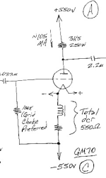
On your schematic, the output tube grid and cathode are both at the same -495 VDC.
This is not correct.
Check each wire and connection involving the filament supply and its connection to the output tube cathode.
There must be a mistake that opens the connection of the output tube cathode to the negative supply.
Or one side of the cathode/filament is shorted to ground. Check the inductor and resistor for continuity
or a short to ground.
Last edited:
Thanks, I will.
2 things to be clear:
1) the filament supply for v2 should float, that is, it should not be connected to the mains ground. Correct?
2) would I get these results if the - of the filament of v2 is in fact the plus?
2 things to be clear:
1) the filament supply for v2 should float, that is, it should not be connected to the mains ground. Correct?
2) would I get these results if the - of the filament of v2 is in fact the plus?
Yes, the filament supply itself must float, and only be connected to the filament.
Follow the data sheet for proper filament connection. Look for an example circuit diagram.
You must have an error in this connection area.
Follow the data sheet for proper filament connection. Look for an example circuit diagram.
You must have an error in this connection area.
yes, the filament supply is floating.
I will check the wiring to verify that it is correct. Thanks.
I will check the wiring to verify that it is correct. Thanks.
The filament supply is floating, i.e. not connected in any way to the mains ground.On your schematic, the output tube grid and cathode are both at the same -495 VDC.
This is not correct.
Check each wire and connection involving the filament supply and its connection to the output tube cathode.
There must be a mistake that opens the connection of the output tube cathode to the negative supply.
Or one side of the cathode/filament is shorted to ground. Check the inductor and resistor for continuity
or a short to ground.
There is continuity from the neg. supply to the neg. filament of the tube as there should be.
Where/how else can the cathode/filament be shorted to ground? And when you say ground, are you referring to the neg. of the rectifier? Is that considered a "ground"?
How about ignore the schematic, and taking a blank piece of paper, look at the wiring, and drawing the circuit
as it exists in your amplifier. Then we will compare the drawing to the correct schematic.
There is a miswiring or connection problem that you are overlooking.
Either there is an open, or a short, that is being overlooked.
If the tube current is zero, but the cathode resistor burns up, it's probably a short to ground
in the cathode or filament circuit.
Last edited:
I’m convinced that OP is either someone testing an AI or an alien pretending to be human. This thread has never made any sense.
This is an interesting idea/ exercise and I will do it though it may take so me time to get to it.How about ignore the schematic, and taking a blank piece of paper, look at the wiring, and drawing the circuit
as it exists in your amplifier. Then we will compare the drawing to the correct schematic.
There is a miswiring or connection problem that you are overlooking.
Either there is an open, or a short, that is being overlooked.
If the tube current is zero, but the cathode resistor burns up, it's probably a short to ground
in the cathode or filament circuit.
In the mean time, can you tell me what is happening/not happening in the circuit? It would help me understand the process and perhaps it might lead me to look in areas of my amp/wiring that I may have overlooked.
Thanks.
Well, I did more than than your suggestion which is why it took me so long to get back to you and now I feel much more confident that the problem is elsewhere and not in my wiring.
Having said that, I want to confirm my suspicions: I have attached the present schematic and with it I would like to know where exactly I should measure the cathode voltage. Also (and more importantly), what should the voltage be at that spot given that there is a plus and minus voltage going into the tube?
Thanks in advance.
Attachments
- Home
- Amplifiers
- Tubes / Valves
- dual power supply