@Vunce Is it this post? 😎 https://www.diyaudio.com/community/...st-tht-i2s-input-nos-r-2r.354078/post-6516751
It was never linked on the first page, but it can be now 😉
It was never linked on the first page, but it can be now 😉
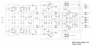
Ordering from a competent person, a fee is PCB according to the following scheme (fees are only sold, there are no gerberas). They are very praised for how it sounds. One "but", it uses BUF03 and is the most preferred, but they have not been produced for a long time and are rare, but there is a minimum order of 18 pieces for our beloved Rotchester Electronics. If there were enough people willing, Paddy would have ordered. I think the Miro DAC will sparkle with new colors with this output, according to reviews, this output with R2R is very much praised.
Attachments
Hi,
Not so sure. Old design nowadays. Do you need a headphone Dac maybe ?
opa861 is better than the AD844 for the task and simplier, then the BUF03 can be sometimes hard according what you have in your hifi, there are today fresher oaps for a buf. And very cool discrete stages have been tested in the thread... And a X7R cap with a LM317... bouhhhhhh !
I would see more something as I described with a proper decoupling for the opa861 at I/V then a modern buffer like the single opa825 to stay smd and compact or two modern Toshibas if a buf is really needed as a single opa861 per channel should suffice with most of amp/pre...
Better (harmonics profile)? Sorted out transistor for a discret I/V : EUVL tested already inthe thread.
Last edited:
@Traktorist3d Interesting I/V, low impedance input stage from AD844 is used and the output stage is bypassed (pin5). This conversion looks like passive (resistor R1). This connection can be tested on a breadboard PCB and can be compared with another I/V. ☕
What is your option with a ready-made PCB board? Over time, I will collect both, I will compare .... Over the course of several years))...time lost imho VS the opa861... we know the two chips very well from a long time now.
Vunce made a pcb for the opa 861 you can use with Miro's board. Both posted the gerbers in the thread.What is your option with a ready-made PCB board? Over time, I will collect both, I will compare .... Over the course of several years))
Sure, do what you want, but I just advért that AD844 was a lot benchmarked vs opa861 and the former never won while being more expensive and eventually needs stacking. So imho better people spend monney where it is both less expensive and better sounding...you know it is a limited world where we live now. But your freedom YMMV.
It is not entirely clear from the diagram what to connect to, one board, one channel, if I am not mistaken, is it connected immediately to the output of the AD1862? Or as an addition to what is in the Miro DAC?Vunce made a pcb for the opa 861 you can use with Miro's board. Both posted the gerbers in the thread.
Sure, do what you want, but I just advért that AD844 was a lot benchmarked vs opa861 and the former never won while being more expensive and eventually needs stacking. So imho better people spend monney where it is both less expensive and better sounding...you know it is a limited world where we live now. But your freedom YMMV.
Yes one 861 Vunce board per channel .They swap the pcb oaps
And they do not share the 12V as tjey need 5V.
And they do not share the 12V as tjey need 5V.
Got that covered Iggy with the onboard LDO regulator so you can use the supplied +/-12vdc from the opamp socket positions 4 & 7. Regulation down to +/-5vdc is done by a single TPS7A39xx chip. 👍
Yes, I would still have to make sure that the kerchiefs are inserted into DIP8 without wires, like my main power stabilizers ..
It turns out that for these output cards you need to remove C31, R8, C36, R9 from the main circuit?
It turns out that for these output cards you need to remove C31, R8, C36, R9 from the main circuit?
Regarding the stock Miro IV and reconstruction filter, has anyone fooled around with supplying the op amps more than +/-12v?
It appears that the 12v value is mandated by the AD1862, but in my case the analog sections are powered separately.
I realize this is not directly comparable, but my experience modifying guitar pedals to run on 12-18v supplies as opposed to 9v suggests that voltage supplies can make significant differences
flak monkey, those are nice boards.
Did you have to order a minimum quantity of boards from JLCPCB?
Which one of the many layouts is the one you ordered, as I am looking for a computer usb >I2S>Dac>pre>amp type of format.
MM
Did you have to order a minimum quantity of boards from JLCPCB?
Which one of the many layouts is the one you ordered, as I am looking for a computer usb >I2S>Dac>pre>amp type of format.
MM
There is a MOQ but I ordered extra above that too as it cost so little to do so. I have 10 of each board and am in the UK.flak monkey, those are nice boards.
Did you have to order a minimum quantity of boards from JLCPCB?
Which one of the many layouts is the one you ordered, as I am looking for a computer usb >I2S>Dac>pre>amp type of format.
MM
I used the board configurations in the linked post here: https://electrodac.blogspot.com/p/dac-ad1862-almost-tht-i2s-input-nos-r.html
I am sure someone more knowledgeable than me will be along shortly, but my input on your requirement would be the following boards from this thread:
DAC: https://www.diyaudio.com/community/...st-tht-i2s-input-nos-r-2r.354078/post-6488132
PSU: https://www.diyaudio.com/forums/dig...-ad1862-tht-i2s-input-nos-2r-post6530268.html
Either the USB to I2S board: https://www.diyaudio.com/community/...2s-input-nos-r-2r.354078/page-85#post-6574952 or a generic one from Aliexpress/eBay etc
I am building up a DAC with a built in Raspberry Pi (to use as a Roon endpoint) as well as Coax and Optical inputs to connect some other stuff to.
Flak monkey....nice purple boards! I have the 12mhz crystals (UK) if you need one?
Also have the optical receiver that fits the board but I believe there is a voltage discrepancy....it may work or you could cut the trace and rehash it. If you want either let me know.
Also have the optical receiver that fits the board but I believe there is a voltage discrepancy....it may work or you could cut the trace and rehash it. If you want either let me know.
Thanks! Had to do something different with the boards, not that anyone ever sees them beyond the build!Flak monkey....nice purple boards! I have the 12mhz crystals (UK) if you need one?
Also have the optical receiver that fits the board but I believe there is a voltage discrepancy....it may work or you could cut the trace and rehash it. If you want either let me know.
I think I have everything I need for the build, but thank you for the offer!
@flak monkey Nice PCBs, happy building 
Did you order corrected PCB for the I2S inputs selector? https://www.diyaudio.com/community/...s-input-nos-r-2r.354078/page-146#post-6868316 ... if you ordered the older version (from post #2526), please make the button correction.
For the SPDIF/Optical to I2S do the correction: DATA and LRCK is swapped #2450, don't use GP1FAV50RK0F as optical input (it is 5V) use alternative for 3.3V (@jimk04 used TORX147)
Thanks, yes I ordered the corrected I2S input selector board 🙂 and thanks for the heads up on the DATA/LRCK correction - I do remember reading that and was going to ask if that was still applicable or if the files had been updated since that comment.@flak monkey Nice PCBs, happy building
Did you order corrected PCB for the I2S inputs selector? https://www.diyaudio.com/community/...s-input-nos-r-2r.354078/page-146#post-6868316 ... if you ordered the older version (from post #2526), please make the button correction.
For the SPDIF/Optical to I2S do the correction: DATA and LRCK is swapped #2450, don't use GP1FAV50RK0F as optical input (it is 5V) use alternative for 3.3V (@jimk04 used TORX147)
I ordered a 3.3v optical input - on a slow boat from China 😆
I got the PSU built up this afternoon

- Home
- Source & Line
- Digital Line Level
- DAC AD1862: Almost THT, I2S input, NOS, R-2R