Thanks for the answers to my prior questions. Here is another one re chassis grounding on the Pearl 2 unit (not the PSU). On 6L6's build, there is a floating binding post on the back panel for the turntable ground. The grounds from the two boards are also connected there (orange wire and black wire in 6L6's photo). The binding post is then star grounded via another black wire to a connection point on the bottom of the chassis. My question is, what is the reason for the separate connection point on the bottom of the chassis? Rather than floating the binding post on the back panel and running the wire to the separate grounding point on the bottom of the chassis, why not just chassis ground everything at the binding post on the back panel and eliminate the connection point on the bottom of the chassis?
I did all grounding on the binding post. Binding post is part of chassis. Wire from center of each board. That’s it. Dead quiet.
flip69 - I floated the post off the chassis (and connected it to chassis in a different place) because grounding is funky, and sometimes it does not go as planned. Isolating the post gave the option to have it isolated from chassis if needed.
It wasn't needed.
🙂
It wasn't needed.
🙂
Thanks jackinnj for the advice, I already ordered a CL-60. Can you please help me with where in the schematics of the PS I need to add this part?You get a surge in current charging up the electrolytic capacitors at "turn-on". This can be mitigated with a Amphenol Thermometrics "Inrush Current Limiter" -- when cold the resistance is high, limiting the charge current. As the ICL heats the resistance decreases. I think that some have used the CL-60 which is readily available at DK.
Link from Amphenol Thermometrics website: https://www.ametherm.com/inrush-current/ptc-thermistors-for-inrush-current-limitingThanks jackinnj for the advice, I already ordered a CL-60. Can you please help me with where in the schematics of the PS I need to add this part?
Hi, has onyone else here recently ordered Nelsons Pearl II boards to Germany?
How long did they got stuck at customs? And did you receive a letter for taxes,.. or were they directly delivered?
I´m asking, because mine are in Frankfurt for 2 weeks now..
Thanks
How long did they got stuck at customs? And did you receive a letter for taxes,.. or were they directly delivered?
I´m asking, because mine are in Frankfurt for 2 weeks now..
Thanks
I also had a bad experience but in Romania not Germany, my bords got stuck in the customs for 3 weeks. Problem is despite the hefty 40 USD delivery charge to Europe the guys at Passdy used USPS which is the standard mail service in the US and when enters another country need to be taken over by the standard mail service in that country and it gets slow in the customs. In your case it would be Deutsche Post.Hi, has onyone else here recently ordered Nelsons Pearl II boards to Germany?
How long did they got stuck at customs? And did you receive a letter for taxes,.. or were they directly delivered?
I´m asking, because mine are in Frankfurt for 2 weeks now..
Thanks
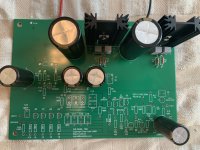
I am advancing with my build. I followed the advice on this forum to start with the regulators part of the board to obtain 24V.
Today finished that part of the build for both boards and I measured:
Board 1: ground to R3 = 23.9 V
ground to R33 = 23.6 V
Board 2: ground to R3 = 23.9 V
ground to R33 = 23.9 V
I assume all is fine but it would be nice a confirmation from the experienced folks here.
One question: now to continue on the build I just solder all the remaining components or is there another step intermediate to follow and then measure certain voltages before continuing ?
Thanks!
Attachments
Also the USPS tracking - at least from my experience - stops at the customs - I could use their tracking number in the Romanian mail service to continue tracking the package. You will need to pay VAT.I also had a bad experience but in Romania not Germany, my bords got stuck in the customs for 3 weeks. Problem is despite the hefty 40 USD delivery charge to Europe the guys at Passdy used USPS which is the standard mail service in the US and when enters another country need to be taken over by the standard mail service in that country and it gets slow in the customs. In your case it would be Deutsche Post.
thanks for sharing your experience. DHL/ Deutsche Post is already aware of the parcel ,I can find it in the tracking System,but I'm waiting for customs clearance and want to avoid the Boards to be returned to the US. and yes, the 40$ are hefty, especially if it takes 3weeks to leave the the US..Also the USPS tracking - at least from my experience - stops at the customs - I could use their tracking number in the Romanian mail service to continue tracking the package. You will need to pay VAT.
Lets hope the Best..
I assume there is no other intermediate soldering step...I need to place all the remaining components and than measure all the voltages?I am advancing with my build. I followed the advice on this forum to start with the regulators part of the board to obtain 24V.
Today finished that part of the build for both boards and I measured:
Board 1: ground to R3 = 23.9 V
ground to R33 = 23.6 V
Board 2: ground to R3 = 23.9 V
ground to R33 = 23.9 V
I assume all is fine but it would be nice a confirmation from the experienced folks here.
One question: now to continue on the build I just solder all the remaining components or is there another step intermediate to follow and then measure certain voltages before continuing ?
Thanks!
Thanks.
Boards have arrived 🙂 4weeks to leave the US, 2 and a half to pass customs. glad that it was priority Mail ;-) will Post Updates on the build herethanks for sharing your experience. DHL/ Deutsche Post is already aware of the parcel ,I can find it in the tracking System,but I'm waiting for customs clearance and want to avoid the Boards to be returned to the US. and yes, the 40$ are hefty, especially if it takes 3weeks to leave the the US..
Lets hope the Best..
Hello Guys, really need your help. I am advancing very good on the 2 boards, only a few components to solder for this weekend and chassis will also arrive this week.
I want to pull the trigger on a turntable. From the 2 finalists I have found a good price on Marantz TT-15S1.
It comes with a Moving Magnet Clearaudio Virtuoso Ebony Wood Cartridge.
I assume I cannot use the stock Pearl 2 for this cartridge.
Can you please help on the custom component's values that I need to change in order to use this MM cartridge?
Specs:
Moving-magnet phono cartridge.
Stylus profile: Not specified.
Frequency range: 20Hz-20kHz.
Output voltage (1kHz, 5cm/s): 3.6mV.
Channel separation (1kHz): >30dB.
Channel balance (1kHz): <0.2dB.
Trackability: >90µm.
Recommended tracking force: 2.0-2.5gm.
Electrical impedance (1kHz): 660 ohms.
Coil inductivity: 0.42mH.
Load resistance 47k ohms.
Load capacitance: 100pF.
Cantilever: aluminum.
Thanks.
Wire per normal -- you will note from the schematic that there are position for two caps, C9 and C16 around R16, only one of which is used. You can put a resistor in parallel with R16 to reduce the gain and minimize the potential overload in the output stage. Listen first, if you find it overloads then wire in the parallel resistor if there is a problem. (The first stage will not overload). JackCan you please help on the custom component's values that I need to change in order to use this MM cartridge?
I checked now the boards and the BOM. I have used both C9 and C16, I think you meant C15 which is near R16 and which I did not use?Wire per normal -- you will note from the schematic that there are position for two caps, C9 and C16 around R16, only one of which is used. You can put a resistor in parallel with R16 to reduce the gain and minimize the potential overload in the output stage. Listen first, if you find it overloads then wire in the parallel resistor if there is a problem. (The first stage will not overload). Jack
Housings, most of the components and Nelsons Boards have arrived. So, startet building..
Edit: Attaching pictures seems not to work With Android? Any hints?
Edit: Attaching pictures seems not to work With Android? Any hints?
Hi guys!
Quick question about C5, C6, C24 and C4. Do these really need to be 35V rated? Isn’t 24V the maximum voltage they will see and 25V rated would be enough?
sorry if this is answered earlier in the thread, not able to search the forum via google after the update.
Quick question about C5, C6, C24 and C4. Do these really need to be 35V rated? Isn’t 24V the maximum voltage they will see and 25V rated would be enough?
sorry if this is answered earlier in the thread, not able to search the forum via google after the update.
- Home
- Amplifiers
- Pass Labs
- Building a Pearl 2