Yup, me too. Almost completed Aleph J, after it will be time for Ultralite for bedroom setup. 
Hi all,
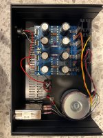
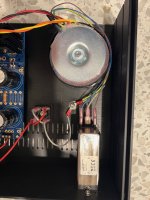
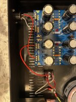
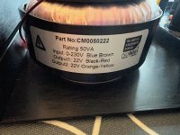
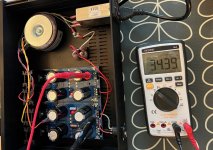
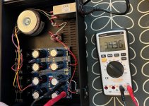
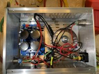
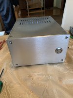
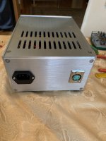
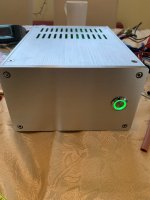
I've finally finished building the power supply with my son, taking longer than expected. A really neat project and great learning for people who have never built anything electronic before. I have not switched the power supply on yet, I would like to ask the community if anyone sees any major blunders with the wiring in the attached photos before I plug in and test the voltages?
Best wishes
Greenwich
Attachments

Be aware all who have built or will build this phono preamp.
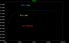
The RIAA response is quite a bit off owing to incorrect resistor value. Refer to the schematic where resistor R13 at 100K is actually in parallel with resistor R11 at 6K8.
The measurements were done using one of our Audio Precision's where I have RIAA tests with the limits set at +/-0.25dB or at +/-0.1dB.
The LF response was way off. Increased R13 from 100K to 1Meg and this cured the problem
I also removed the 24v regulators and put in discrete low noise, low output Z regulators. Jung regs will also work fine.
Added 47R5 source degeneration resistors to Q4 and Q5 for a little extra stability and paralleled R10 with a 1mfd WIMA PP cap.
Lastly I added a 2 pole servo to the final amplifier and eliminated C8 and C13.
Zed Audio
Attachments
I don't think that's correct. The error is R12 which, on the schematic is 909 Ohms, a typo I believe. The correct value should be 990 Ohms which can be derived from two parallel resistors. See these simulations. Buried in this thread are my actual measurements, also done on an AP SYS2722Be aware all who have built or will build this phono preamp.
The RIAA response is quite a bit off owing to incorrect resistor value. Refer to the schematic where resistor R13 at 100K is actually in parallel with resistor R11 at 6K8.
Attachments

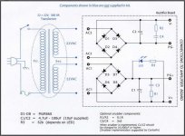
Has anyone measured how much current is drawn on the positive respectively negative rail?
I'm starting with the bild of the powersupply soon, but with one diode bridge only first.
Therefore I Would like to add some resistors for additional consumption..
Thanks, Dobbeln
I'm starting with the bild of the powersupply soon, but with one diode bridge only first.
Therefore I Would like to add some resistors for additional consumption..
Thanks, Dobbeln
I have just finished my Pearl 2 power supply. I am getting 32.3V both sides, assume this is in the correct range?
Also, after I finished the build burned 2 x 0.5 A fuses and than 2 x 1A fuses. I admit that they all burned while playing to the power on/off button by clicking on -off - on to see the green light lit and the PS working 🙂
The 3rd 1A fuse holds if I do not play with the button... I do not know the phenomena behind, question is if I should go for a higher value fuse? I live in a 220V country.
On a side note today my Pearl 2 boards from US have arrived, I will start by build soon.
Attachments

You get a surge in current charging up the electrolytic capacitors at "turn-on". This can be mitigated with a Amphenol Thermometrics "Inrush Current Limiter" -- when cold the resistance is high, limiting the charge current. As the ICL heats the resistance decreases. I think that some have used the CL-60 which is readily available at DK.I have just finished my Pearl 2 power supply. I am getting 32.3V both sides, assume this is in the correct range?
Also, after I finished the build burned 2 x 0.5 A fuses and than 2 x 1A fuses. I admit that they all burned while playing to the power on/off button by clicking on -off - on to see the green light lit and the PS working 🙂
The 3rd 1A fuse holds if I do not play with the button... I do not know the phenomena behind, question is if I should go for a higher value fuse? I live in a 220V country.
On a side note today my Pearl 2 boards from US have arrived, I will start by build soon.
For 6L6, Peter Daniel, or anyone else who has used Peter's PSU board, is the LED required as part of the circuit, like it is on the Pearl 2 board, or is the LED space provided simply as an option for a power on/indicator light?
Hello Guys, I need your help to replace a part that is out of stock in both DK and Mouser.
It is Q1-Q3-Q10-Q11 - ZTX450.
I can only find at Mouser ZTX450STZ - it seems identical, I cannot pick up the difference.
Can you please let me know if the replacement is OK to avoid any screw up?
Thanks.
It is Q1-Q3-Q10-Q11 - ZTX450.
I can only find at Mouser ZTX450STZ - it seems identical, I cannot pick up the difference.
Can you please let me know if the replacement is OK to avoid any screw up?
Thanks.
It's optional. See the schematics attachedFor 6L6, Peter Daniel, or anyone else who has used Peter's PSU board, is the LED required as part of the circuit, like it is on the Pearl 2 board, or is the LED space provided simply as an option for a power on/indicator light?
Attachments
R12 question:
After lots of readings I am not clear what is the correct info regarding this resistor
In the forum I have found both - that 909 is a typo and 990 is the correct value but also that 909 is correct value and for 990 improvement other component values need to be changed.
I have ordered all the components based on the newer Excel BOM with R12 = 990 but in this Excel the other components mentioned on the forum that need to changed still have the original Pass Lab BOM values.
What is the correct R12 value for stock build?
After lots of readings I am not clear what is the correct info regarding this resistor
- original Pass Lab BOM = 909 R
- older Word BOM = 909 R
- newer Excel BOM = 990 R
In the forum I have found both - that 909 is a typo and 990 is the correct value but also that 909 is correct value and for 990 improvement other component values need to be changed.
I have ordered all the components based on the newer Excel BOM with R12 = 990 but in this Excel the other components mentioned on the forum that need to changed still have the original Pass Lab BOM values.
What is the correct R12 value for stock build?
909 ohms will give a little lift in the upper bass (baritone) range and some people like that. the most important thing about the RIAA comp is that the channels should line up on top of each other. It's only a difference of 0.2dB
- Home
- Amplifiers
- Pass Labs
- Building a Pearl 2