Another SG4 Project Starting in Earnest
I recently started an AR-XB turntable restomod project and discovered this project. Of all the AC Synchronous motor controller designs I have come across in the last few days, Pyramid’s SG4 sine wave generator was the most appealing to what I think I need to control the speeds of my turntable.
I have the purple boards on order from Osh Park for the SG4, Encoder, and Sensor (yeah, a tachometer will be cool), and my first order has been placed with Mouser.
I can’t wait to get to work on this!
-Glen
Wanted: Rotary Encoder PCB Thru-Hole for use with SG4
I butchered the surface mount version of the Rotary Encoder PCB. Does anyone have an extra thru-hole version? Thanks in advance.
I butchered the surface mount version of the Rotary Encoder PCB. Does anyone have an extra thru-hole version? Thanks in advance.
SG4 Complete!
Keeping this thread alive, I completed my SG4 and it powered up the first time today without issue.
Next step is to wire it up to the TDA7492 and 2 Amgis L01-6362 12V toroid transformers to power a 2 phase Hurst motor on my AR turntable.
Keeping this thread alive, I completed my SG4 and it powered up the first time today without issue.
Next step is to wire it up to the TDA7492 and 2 Amgis L01-6362 12V toroid transformers to power a 2 phase Hurst motor on my AR turntable.
Attachments
Hi, first of all, thanks Pyramid for this d.i.y. project. The pics below are of my second attempt. Iv'e been using my first one for over a year now it has worked beautifully the whole time. This version fits into a Naim shoebox sleave. and has simple controls, power knob, (m)on-off-on toggle switch for start 33 and 45 speeds. It has afew resistors to drop the voltage between the sg4 board and the amplifier. Fac. reset puts the output voltage at 90 volts The main transformer is 50 va , the step up transformers are 15 va each. works perfectly, very pleased. Thanks again Mr Pyramid.


Last edited:
I don't know how to edit the above post so I'll post an update here.
My build stopped working, there was a ticking sound coming from the output transformers. The amplifier was struggling so I have altered the resistors between the signal generator and amp, maximum output is now 75 volts. Working nicely again.
My build stopped working, there was a ticking sound coming from the output transformers. The amplifier was struggling so I have altered the resistors between the signal generator and amp, maximum output is now 75 volts. Working nicely again.
If the output amps are "ticking" they are shutting down because they see to much of a load at start up. The SG-4 ramps up the voltage when it comes out of standby to prevent this.
It looks as if the low voltage windings of the output xfmrs are in parallel, so a 7V secondary? The turns ratio will be 115V divided by the unload secondary voltage if hooked up normally which would be ~9V, so the turns ratio is ~12.77:1. The load seen by the amps will be the motor impedance transformed by the square of the turns ratio. If you put the 7V windings in series instead, the turns ratio will be cut in half and load seen by the amps will increase 4x and be easier to drive. In bridge configuration, you will need ~25VPP into the secondaries to get 115VAC out (unloaded); with a 24VDC supply the most you will be able to get is ~107VAC out which should be OK.
You will need to increase the drive level between the SG4 and the amps to get 24VPP to the output xfmrs.
Pyramid, thanks for your advice, even though I'm almost an old man I'm relatively new to electronics, and quite often use guesswork. Yes the transformers are wired in parallel, I was thinking that if I wired the 7 volt side in series i would need twice the voltage from the amplifier, I was just guessing that the amplifier would only supply about 6 volts max. So what you are saying is double the impedance therefore halving the current from the amplifier but also double the voltage from the amplifier. I'll have a twiddle tomorrow. Thanks again.
So what you are saying is double the impedance therefore halving the current from the amplifier but also double the voltage from the amplifier. I'll have a twiddle tomorrow. Thanks again.
Actually, it will quadruple the impedance which will make it easier to drive, especially at start up. In bridge configuration, the applied voltage is effectively doubled, but the impedance seen by the amp is cut in half, exacerbating the problem and why it is better to have a higher impedance load.
The TDA7294 chip amps are rated for 26VDC max; what is the supply voltage you have for the amps? They are able to drive the outputs to the supply rail, so a 24V supply can achieve 24VPP; with a bridge amp, this equates to 17VRMS, close to the unloaded output of a 14V secondary.
Bill, thanks for pointing me in the right direction, your advice is appreciated. The input side of my output transformers are now wired in series, my voltage divider between the signal generator and the amplifier is dropping the amplifier output to 13volts and my transformers are measuring 100 volts. I'm very happy with that. Thanks again. Rob.
A number of people have inquired about using an LCD display with the SG-4 sinewave generator. I've updated the PCB and firmware to allow both LED and LCD displays concurrently. The link to Oshpark for the PCB has been updated in the O/P as well as a brief description. It is very difficult to add new attachments to the OP, so I will post those here and add a link to this post in the O/P.
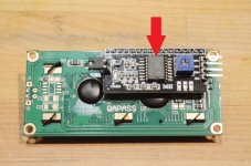
The SG-4 will now have 4 additional pins to interface with an I²C capable 2 line x 16 character LCD module. The LCD module should have an I²C interface attached that utilizes the PCF-8574A interface chip. There are 3 address pins (jumpers) on these PCBs that should all be open (all high) in order for the SG-4 to correctly address the chip. The modules have a 4 wire interface: Gnd, Vcc, SDA, and SCL; the Rev B SG-4 PCB now has these 4 output pins that can be directly wired to the LCD I²C interface PCB.
The LCD capability requires firmware version 1.04 which is also backward compatible with the original (Rev A) SG-4 PCBs. To add an LCD display to the previous version SG-4 PCB, make the 4 connections as shown in the attached PDF (SG4 I2C Interface.pdf).
Both displays can be run concurrently. If the LED display is not needed, U3, DS1, R10-R17 and Q1-Q4 can be left off the PCB. The functionality of the SG-4 remains exactly the same as version 1.03 firmware; version 1.04 adds only the LCD display routines.
The second line of the LCD displays the speed and frequency as well as "Stand-by". In reduced voltage and phase adjust modes, the second line of the LCD displays the speed and voltage or phase.
The top line of the LCD can display 16 characters of free form text; the default text is "SG-4 v1.04" but can be customized by the user to display any English characters the LCD is capable of including A-Z, a-z, space and all punctuation characters. Operation of the customization mode has been added to the assembly instructions (attached to this post). In order to initialize this message on a previous build (updating from firmware v1.03 to v1.04) you must do a factory default reset after installing the new firmware.
Attachments
This is great news. I've built 5 or 6 SG4 and think it's better than sliced bread...
Do I need to purchase new microprocessor chips or can I upload new firmware?
Are you going to publish the new Gerber files? I find JCLPCB to be a lot cheaper than OSKPark
Many thanks for your efforts!
Do I need to purchase new microprocessor chips or can I upload new firmware?
Are you going to publish the new Gerber files? I find JCLPCB to be a lot cheaper than OSKPark
Many thanks for your efforts!
It's probably easier and cheaper to just buy new chips, it will be less than the postage both ways. I don't release the IP to the public and it would take a programming device to reload the chips.
If you have a lot of chips that need to be updated, PM me and you can send them to me for reprogramming (US only).
The only difference on the PCB is the addition of a 4 pin header for the LCD (Gerbers attached). It is relatively easy to wire a cable for the LCD directly to the original PCB if you want to retro-fit one (see SG4 I2C Interface.pdf in previous post).
Attachments
Last edited:
And, yes I do see that connecting to the existing PCB is very easy. I still have a couple of these so probably won't bother to order new ones.

Good news is, nothing is obsolete with those PCBs. The new firmware will work with the LED only display or an LCD display can be added with ease to the existing PCB, just hardwired to the appropriate pins. Seth and Ralph have the updated firmware so anything they ship at this point should be forward and backward compatible.
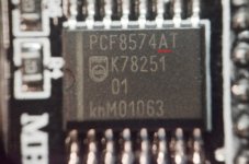
I just received a question that needs clarification: The I²C interface chip for the LCD display must be type PCF-8574A, not PCF-8574. The two chips work nearly the same but have different address schemes; only the PCF-8574A chip will work with the SG-4 firmware change.
The 'A' series chips will have addresses 038h-03fh; the non-series 'A' chips will have addresses 020h-027h on their instruction sheets.
The 'A' series chips will have addresses 038h-03fh; the non-series 'A' chips will have addresses 020h-027h on their instruction sheets.
Attachments
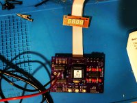
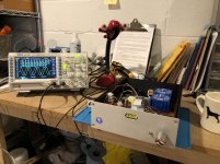
Thanks to all the great notes on this and the other SG4 amp thread, and Pyramid’s excellent design, my SG4 is finally up and running! I notice that the frequency, as measured on my Oscope, dances around a little. I warmed up the SG4 for an hour to see if it stabilized, but I still saw the same little dance between 59.8hz and 60.2hz. The display on the SG4 holds steady at 60.00Hz. Is that normal?
I used the TDA-7492 Amp in my build.
I used the TDA-7492 Amp in my build.
Attachments
- Home
- Source & Line
- Analogue Source
- DIY 4 Phase Sinewave Generator for Turntable Motor Drive