PM Seth Hansel. It’s explained on post #1
Thanks, had tried that a week or so back, but no luck, didn't know if the arrangement had changed.
Hi Everyone,
I’m just currently building the SG4 but have got very confused as to which way to insert the MCP101-450HI/TO
Searching through the thread I found some info from Pyramid that says its the mirror image of the DS1833. The datasheets seem to say that for the DS1833 pin 1 is gnd, pin 2 is rst and pin 3 is vcc and for the MCP101-450HI/TO pin 1 is vss, pin 2 is rst and pin 3 is vdd.
I checked on Wikipedia because I don’t know the difference between vcc,vss and vdd and found that vcc seems to be equivalent to vdd and vss is not equivalent to gnd but more negative than vdd.
All of this seems to indicate to me that the pin outs of the the two packages is the same. So I’m confused as this contradicts the earlier advice.
Can any one point me in the right direction?
Many thanks!
For the MCP101-450HI/TO, pin 1 is Vcc, pin 2 is Reset and Pin 3 is gnd, so it is the mirror image of the DS1833. You have to make sure you have the "H" suffix; a "D" suffix (MCP101-450DI/TO) is different.
Thank you so much for responding to me, for some reason I now see my mistake! I hadn't noticed that the diagram I was looking at for the DS1833 was from the bottom (although it clearly says so)!

Regards all.
Does anyone have any built board set, or either of the 2, available for sale?
Already have the BLWS motor.
Thanks
Does anyone have any built board set, or either of the 2, available for sale?
Already have the BLWS motor.
Thanks
Hi folks, was wondering if anyone knew of a way to turn off the 7 segment display? Looking to implement a simple switch to ground to do this, but not sure if this is possible with the SG4 LED controller? I brute forced it in the code for the Arduino tach off of a switch to ground, and would like a way to dim both displays once everything is running for those night time listening sessions.
Pin 10 of U3 is tied to Vcc. Cut the trace and add a 10K resistor between Vcc and pin 10. Ground pin 10 to turn off the LED display.
Great, thanks Bill. Read up on SRCLR and understood.
The SRCLR pin allows us to reset the entire Shift Register, making all its bits 0, at once. This is a negative logic pin, so to perform (or maintain) this reset we need to set the SRCLR pin low. When no reset is required, this pin should be high (Vcc).
The SRCLR pin allows us to reset the entire Shift Register, making all its bits 0, at once. This is a negative logic pin, so to perform (or maintain) this reset we need to set the SRCLR pin low. When no reset is required, this pin should be high (Vcc).
Display only shows segments
Just completed the SG4 and I am having some display issues and am hoping someone can point me in the right direction. The display when the ac is toggled on/off shows the top segment on all 4 numbers. Keep turning on/off and it shows number 8 with the top bar missing. Keep turning on/off I get ‘C’s’, U’s, A’s at random. Nothing shows differently when I press up, down, stby. Voltages are all in spec on U ic’s.
I bought 2 uP and the same happens with either installed. I reflowed all solder points and check with a magnifying glass. Any help is greatly appreciated.
The display when the ac is toggled on/off shows the top segment on all 4 numbers.
The input to the PCB should be 12VDC not AC (unless that's a typo).
If the LEDs display the same random characters on all 4 digits, the uP is not running. This will happen if the processor is stuck in reset (or never properly reset at power up), if the crystal is not oscillating or it is connected improperly.
If the input is DC, check the reset circuit; the input to U4 should be 5VDC and the output going to pin 10 of the uP will be 5VDC for ~350mS at power up then drop to ground.
If you have a scope, check that the crystal is oscillating at 18.432MHz at pin 20 of the uP.
Make sure the uP is inserted correctly and is seated all the way in the socket. Check that there are no bent contacts on the socket before inserting the chip.
Thank you Pyramid
Should have specified AC to power supply. Found that U4 has an intermittent connection internally. If I apply light pressure to the ic, everything works fine. Seems it’s pin 2 to the U1’s pin 10. Ran a separate wire to eliminate any chance the trace was broken and still have the problem. Ordering a MCP101-450HI/TO. Thank you very much for this project and your help. Please be well.
Should have specified AC to power supply. Found that U4 has an intermittent connection internally. If I apply light pressure to the ic, everything works fine. Seems it’s pin 2 to the U1’s pin 10. Ran a separate wire to eliminate any chance the trace was broken and still have the problem. Ordering a MCP101-450HI/TO. Thank you very much for this project and your help. Please be well.
Glad to find this!
Hi Pyramid et al.
Found this thread while doing some research for my upcoming diy turntable build. The motor was the biggest question mark for me. This setup seems ideal!
I messaged Seth for a processor.
If anyone has an extra SG4 or MA-3D pcb kicking around I would be happy to buy them!
Cheers,
Michael
Hello Pyramid
Can the 50Hz freq be varied so to tune the rotation speed on an Ariston Rd80 ?
PS: Just saw the video and it does permit freq finetunning....thank you
Can the 50Hz freq be varied so to tune the rotation speed on an Ariston Rd80 ?
PS: Just saw the video and it does permit freq finetunning....thank you
Last edited:
Controller build (almost) finished. Got pics!
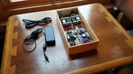
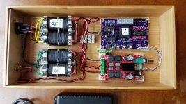
I finished and tested the actual SG4 build a few months ago, but it was all just laid out on a piece of plywood and I was only using one channel b/c I hadn't rewired the turntable yet. Put my head down this week and got things mounted up properly.
The case is a simple 6x12 inch bamboo drawer organizer I got off Amazon. Amp is a 2x50W class-D that was on sale at Parts Express. Power is a 16V SMPS taken from an old IBM/Lenovo laptop.
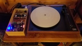
My turntable is an early-80's vintage Rega Planar-2. Purchased from a seller in the UK, the original AC motor was configured for 220V/50Hz operation. I modded the unit to run on 120/60Hz. For this update I removed the internal resistor and cap and rewired the small circuit board for 2-phase operation. It looks stock except for the Neutrix connector on the end of the new power cord. Arm is an Origin Live modded RB250. Nothing fancy but a reasonably decent performer IMNSHO. 🙂
I had to intended to leave the power switch on the front of the deck functional but that didn't work out so well. In the turntable's original single-phase mode with a capacitor, the switch would cut the common power return line. As we all know new supply provides two out-of-phase power leads and the common return. Since the tails of the two coils are tied together before the on-off switch current can pass in on one power lead and return through the other lead. So with the switch off we have effectively wired the coils in series with second one reversed and put ~150VAC across the combination. While probably not enough to get things initially spinning, it is seemingly enough to keep the platter turning. The solution would be to replace the switch with a DPST that would cut the current to both tails separately.
I still have some work to do at this point. I have the rotary encoder board and am figuring out how I want to lay out the front panel. Sharp eyes also will notice the lack of a power switch, lack of an input fuse and the switch to select 45rpm operation is missing (but the leads are there!). Finally, the whole thing needs a cover.
But the fun thing about this hobby is that nothing is ever really finished, is it?
Later,
-b
I finished and tested the actual SG4 build a few months ago, but it was all just laid out on a piece of plywood and I was only using one channel b/c I hadn't rewired the turntable yet. Put my head down this week and got things mounted up properly.
The case is a simple 6x12 inch bamboo drawer organizer I got off Amazon. Amp is a 2x50W class-D that was on sale at Parts Express. Power is a 16V SMPS taken from an old IBM/Lenovo laptop.
My turntable is an early-80's vintage Rega Planar-2. Purchased from a seller in the UK, the original AC motor was configured for 220V/50Hz operation. I modded the unit to run on 120/60Hz. For this update I removed the internal resistor and cap and rewired the small circuit board for 2-phase operation. It looks stock except for the Neutrix connector on the end of the new power cord. Arm is an Origin Live modded RB250. Nothing fancy but a reasonably decent performer IMNSHO. 🙂
I had to intended to leave the power switch on the front of the deck functional but that didn't work out so well. In the turntable's original single-phase mode with a capacitor, the switch would cut the common power return line. As we all know new supply provides two out-of-phase power leads and the common return. Since the tails of the two coils are tied together before the on-off switch current can pass in on one power lead and return through the other lead. So with the switch off we have effectively wired the coils in series with second one reversed and put ~150VAC across the combination. While probably not enough to get things initially spinning, it is seemingly enough to keep the platter turning. The solution would be to replace the switch with a DPST that would cut the current to both tails separately.
I still have some work to do at this point. I have the rotary encoder board and am figuring out how I want to lay out the front panel. Sharp eyes also will notice the lack of a power switch, lack of an input fuse and the switch to select 45rpm operation is missing (but the leads are there!). Finally, the whole thing needs a cover.
But the fun thing about this hobby is that nothing is ever really finished, is it?
Later,
-b
Attachments
Last edited:
One addendum to my earlier post, I started noticing some of the "clicking" that others were experiencing and the platter would fail to start. It was an intermittent fault and not always reproducible. My fix was to modify the input side of the transformer (secondaries) and wire the two legs in series, rather than in parallel as they are shown in the above pics. I left the output side (primaries) in parallel so as to maximize the load impedance seen by the amplifier. This does cut the output voltage in half, but he motor only really needs 60-70 VAC to get started so nudging the amplifier gain up just a bit was sufficient to drive things.
I suspect that reintroducing the series resistance that was part of the original turntable's driver board would have also been sufficient but would have required a separate resistor for each leg.
-b
I suspect that reintroducing the series resistance that was part of the original turntable's driver board would have also been sufficient but would have required a separate resistor for each leg.
-b
I am building a circuit like this one and having trouble when trying to feed the output transformer with 50hz.... it seems my power amp is unable to cope with the low load produced by the 6.3VAC windings when operated with 50hz.
I am wondering if placing a 8 ohm resistor on the output of the power amp (between the power amp and the 6.3VAC transformer winding) might help.
Should any power amp feed an output transformer without series resistance ?
I am wondering if placing a 8 ohm resistor on the output of the power amp (between the power amp and the 6.3VAC transformer winding) might help.
Should any power amp feed an output transformer without series resistance ?
Try using a 12VAC transformer instead of 6.3V. The impedance of the motor seen by the amp is reduced by the square of the turns ratio. The turns ratio will be the input voltage (115 or 230VAC) divided by the UNLOADED output voltage; for 6.3V, it should be ~8-9VAC. This will also require 9VAC input to produce 115/230VAC output UNLOADED, so the input voltage needs to be slightly higher under load to maintain full voltage into the motor.
The impedance seen by the amp will be 4 times lower with a 6.3V xfmr than with a 12.6V xfmr.
A series resistor can help at start up, but 8 Ohms will be to large; depending on the transformed impedance of the motor, the resistor may consume more voltage than the motor.
The impedance seen by the amp will be 4 times lower with a 6.3V xfmr than with a 12.6V xfmr.
A series resistor can help at start up, but 8 Ohms will be to large; depending on the transformed impedance of the motor, the resistor may consume more voltage than the motor.
Thank you very much for the very good information.
I will wire the two 6.3 windings in series.
I will wire the two 6.3 windings in series.
Definitely try running the low voltage input side in series. Are you trying to drive a 2-phase motor? As I mentioned, my Plan B was to add relatively small series resistors (a couple K-ohm) back into the two motor winding legs.
- Home
- Source & Line
- Analogue Source
- DIY 4 Phase Sinewave Generator for Turntable Motor Drive