

Hi, Have soldered all the components in and on first test there is no voltage on Neg. side. Pos. side showing 15.47V Neg. side showing -1, so sad.
Try again to give picture for post#499 viewable ��
Use the attachment to upload pictures 😉
Hi, Have soldered all the components in and on first test there is no voltage on Neg. side. Pos. side showing 15.47V Neg. side showing -1, so sad.
Hi Colin.
Check whether all the components in the negative power supply section are correctly placed. You can also upload some closely taken photos of the power supply section so that we can check whether something is amiss.
Use the attachment to upload pictures 😉
Torvbakkane's images.
Attachments
Hi Colin.
Check whether all the components in the negative power supply section are correctly placed. You can also upload some closely taken photos of the power supply section so that we can check whether something is amiss.
Hi, I have checked the components and found that I had somehow swapped the BD139 for BT 139 oops! I just hope there is no damage further on now.
Torvbakkane , nice built !
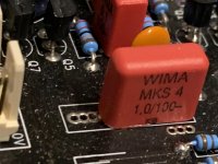
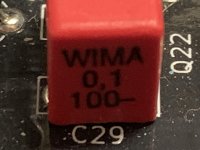
Can you post a picture of those big red (Wima , I assume) capacitors?
Thanks
Can you post a picture of those big red (Wima , I assume) capacitors?
Thanks
Hi Asuslover,
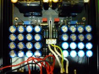
I attach some pictures of the WIMA capacitors, it's like you see the MKS4 I used. There are 10μF, 1.0μF and 0.1μF in the 100V version. Ref. pictures.
I attach some pictures of the WIMA capacitors, it's like you see the MKS4 I used. There are 10μF, 1.0μF and 0.1μF in the 100V version. Ref. pictures.
Attachments

Hi, have now got it set up per your instructions. Unfortunately there is no sound from the left channel, could it be to do with the above? Have I destroyed something down the line maybe?Hi, I have checked the components and found that I had somehow swapped the BD139 for BT 139 oops! I just hope there is no damage further on now.
Hi, I don't know now what the problem was but after playing around with the wiring it is now up and running perfectly. The sound is very detailed and not bright like some modern pre-amps tend to be. I will run it now for a few weeks and let it settle down and just enjoy the music. Thanks!Hi, have now got it set up per your instructions. Unfortunately there is no sound from the left channel, could it be to do with the above? Have I destroyed something down the line maybe?
Hi Colin.Hi, I don't know now what the problem was but after playing around with the wiring it is now up and running perfectly. The sound is very detailed and not bright like some modern pre-amps tend to be. I will run it now for a few weeks and let it settle down and just enjoy the music. Thanks!
Great to know that you got the preamp on track. Please do let us know your thoughts after thorough listening. ^_^
Hi Shaan,
I would like to get two circuit boards of your Pre Amp.
Is it possible ?
Maybe someone else would be interested too.
Thanks !
I would like to get two circuit boards of your Pre Amp.
Is it possible ?
Maybe someone else would be interested too.
Thanks !
Hi Shaan,
I have left the amp powered up for listening, but now the left channel has stopped working. I have tested the power supply etc. and all is OK with that, where to go from here? Colin.
I have left the amp powered up for listening, but now the left channel has stopped working. I have tested the power supply etc. and all is OK with that, where to go from here? Colin.
Hi Colin.
Sorry for keeping you waiting. Why I was away is posted here.
Feel free to send me a couple closely taken pictures of the channel via PM or in here.
Check the continuity between the heatsink of the dead channel and PSU ground. If you are using a loop breaker it should read the same resistance as used in the breaker.
Hi Shaan, Sorry to hear you have been unwell. I traced the problem and now all is fine again and working just as you have described. Thanks.Hi Colin.
Sorry for keeping you waiting. Why I was away is posted here.
Feel free to send me a couple closely taken pictures of the channel via PM or in here.
Check the continuity between the heatsink of the dead channel and PSU ground. If you are using a loop breaker it should read the same resistance as used in the breaker.
Hi Shaan, Sorry to hear you have been unwell. I traced the problem and now all is fine again and working just as you have described. Thanks.

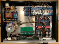
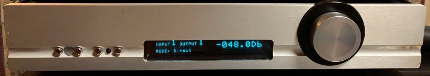
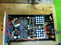
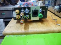
Hi Shaan, I now feel obliged to show some pictures of my effort. I had a bit of a struggle to get it in the enclosure but at this time needs must. It was actually a passive pre I has spare so it was forced into service! I must say also that the SIG control works exactly as you have described in your paper. Thanks for providing me with so much fun and games!
Attachments


- Home
- Group Buys
- PeeCeeBee Preamplifier GB