R1 & 2 are quite high , you're not concerned for their noise ? Is C4 necessary ?
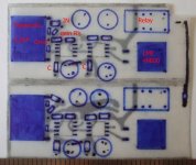
Did you actually make it , or just in spice ?
Did you actually make it , or just in spice ?
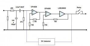
With gains as high as 4 or 5 , I like to use 2 opamps .
Douglas Self does this too , like in the 5532 OpAmplifier in Elektor 10-2010 .
Douglas Self does this too , like in the 5532 OpAmplifier in Elektor 10-2010 .
I dont think noise is an issue with those resistors.R1 & 2 are quite high , you're not concerned for their noise ? Is C4 necessary ?
Did you actually make it , or just in spice ?
C4 is perhaps not necessary, but SPICE shows it makes more stability.
I do not laugh - we are both amateurs.Ok , now don't laugh , I'm just an amateur , but to give you an idea :
I have not built my circuits. It is only SPICE.
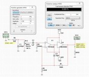
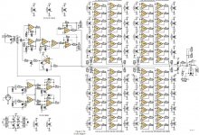
I can not understand the use of 2 OP-amps before the LME49600.
Think that improves nothing.
If Douglas Self does this and in Elektor some others , it is good enough for me. I think it is better to spread the gain between 2 opamps.
The second has to control the LME beast .
2 Opamps = more noise , but if like you who uses 10k as feedback resistor , what's a little more noise ?
The second has to control the LME beast .
2 Opamps = more noise , but if like you who uses 10k as feedback resistor , what's a little more noise ?
The reason for using tantalum caps is to prevent the de-noiser from oscillating, but do so at the possible expense of reduced OPA828 stability?
I'll try first with only the passive components and 0,1uF ceramics , but with 100uF 's E-caps over them I'm breaking Elvee's Law : ratio between the 2 should be between 30 and 100 . It's not easy. 😕
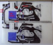
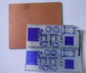
Meanwhile no responce about supply tracks and ground planes under signal tracks and I'm so ready to get started on the epoxy PCB.
Meanwhile no responce about supply tracks and ground planes under signal tracks and I'm so ready to get started on the epoxy PCB.
The Azul HPA had a ground plane on the bottom copper AND a ground pour/fill on the top copper. Worked great. Circuit was a composite amplifier with 55 MHz opamp and 100 MHz high current video buffer enclosed in a single global NFB loop. 2 layer PCB thickness was 0.062" and copper layers were 35 microns thick (standard "1 ounce"). Opamp and video buffer were socketed to make swapping / "rolling" easier. Also allowed powering up and debugging one channel at a time.
If Douglas Self does this...it is good enough for me.
Not so fast, if you please. Mr. Self's work is IMHO worth taking a look at, no problem there. Building a 'blameless amp' may be worth doing too, at least as something to do along the path of gaining experience. Wouldn't suggest to stop there, however. Not everyone agrees on whether Mr. Self's amp design is all that blameless when evaluated by human listening tests, say, as opposed to when evaluated by 'figure of merit' test instruments. What we do know is that figure-of-merit measurements do not completely predict sound quality. Maybe someday we will standardize some tests that might do things such as more finely characterize reproduction of cues needed accurate reproduction of the stereo illusion. Have to wait and see, I guess.
Was that Mr Self circuit really headphone amplifier?If Douglas Self does this and in Elektor some others , it is good enough for me. I think it is better to spread the gain between 2 opamps.
The second has to control the LME beast .
2 Opamps = more noise , but if like you who uses 10k as feedback resistor , what's a little more noise ?
I have and have been using one of OPC's headphone amps since they came out. I changed the gain of mine to 6x due to the low output of my FM tuner and a 3db loss in the balance control. I leave mine on always. Since all of my sources have output coupling caps, I did not see the need for any input caps. Same with my power amps, they have input caps. I use a 10K stepped volume control and a stepped linear 10K for balance. The lme49600 can output more than 250ma and it will run speakers directly, not loud though.
What we do know is that figure-of-merit measurements do not completely predict sound quality.
 Yeah, they do.
It is OK, with some caveats. If the supply lines are noisy (ripple, etc) they can capacitively pollute high sensitivity/high impedance lines.s it ok to have : * supply tracks
* ground lines for decouple caps
* groundplanes that conduct return currents
* and groundplanes that only shield on the other side of the PCB under the opamps .
under the opamp inputs or the feedback (gain) resistors ?
If the inverting input is high impedance, parasitic capacitance to GND (that includes any AC GND like supply lines) can alter the closed-eloop response.
And finally, tracks part of the output loop (supplies) carry class B currents and can induce distortion into tracks that are parallel for a significant distance, just like in a class B power amp
You should avoid that kind of complication, unless it is proven necessary in a real testI know crossing signal tracks with supply tracks is better than paralleling them .
When an input is connected to the low impedance of an opamp output , does it
matter that there is potential supply line noise on the other side of the PCB ?
What if I elevated the power tracks ( and even ground current tracks) so that it is more than the thickness of the 1,5 mm epoxy PCB , like with a wire bridge or in places where they come close , use a piece of PCB on top ( even with a 3rd layer in between connected to the ground to shield ) , so that they are 3 mm apart ?
No. Static magnetism has very little influence on an IC. It can slightly alter the Vbe of junctions or offset voltages, but nothing to worry about unless you have to deal with DC amplifiers processing µV signals.And : Can the coil magnetism of a relay near an amp IC , influence the signal ?
You have to make sure that the magnetic field is actually static though: if the relays are fed from a raw supply, they won't be affected but the field they generate will contain some AC pollution
A few nH is not going to bother a regular opamp, even a very fast one. 50nH could begin to upset some opamps, but it very much depends on the actual situation.On T.I's SLOA068 pg 11 about decoupling high speed opamps , it shows that a 0,4 mm via through a 1,5 mm PCB has an inductance of 1,1nH . My via's are much wider , and longer if I use 2 x 1,5mm PBC , which boosts the nH's .
At what number of nH does that start playing a role in audio circuits , or can it make high speed opamps less stable when decoupling through such via's .
Now I'm using 1mm copper rods , about 3 -4 cm long from the regulator to the opamps/LME.
For 4 cm , that would be about 48,6 nH .
In most of the cases, you'll be able to get away with it, but you might sometimes find yourself in troubles
A search on the site or DDgo for Azul HPA doesn't show much. Was there groundplane under the sensitive area's of the opamps too ?The Azul HPA had a ground plane on the bottom copper AND a ground pour/fill on the top copper. Worked great. Circuit was a composite amplifier with 55 MHz opamp and 100 MHz high current video buffer enclosed in a single global NFB loop. 2 layer PCB thickness was 0.062" and copper layers were 35 microns thick (standard "1 ounce"). Opamp and video buffer were socketed to make swapping / "rolling" easier. Also allowed powering up and debugging one channel at a time.
If you don't use a shared dual opamp for L + R , debugging is not a problem.
Some here mention the overkill of a high current video buffer like LME49600 with 2000V/us , yet NO mention at all on the datasheet . More-over all the applications given are for audio (or power supply). But the datasheet of the BUF634 & A does mention video driver.
No , it was a powerAmp. Same principal just lower power for the HPamp.Was that Mr Self circuit really headphone amplifier?
Attachments
- Home
- Amplifiers
- Headphone Systems
- Anyone make OPA828 - LME49600 combination