One of these days I'll post a PCB layout , but I'm hesitant because it is old school , very old school, no nice visualized PCB in software like I see everywhere here on DIYaudio but on tracing paper 😱... the way I like to draw PCB layouts.
But no real answers to my questions about ground and supply lines under signal tracks.
On T.I's SLOA068 pg 11 about decoupling high speed opamps , it shows that a 0,4 mm via through a 1,5 mm PCB has an inductance of 1,1nH . My via's are much wider , and longer if I use 2 x 1,5mm PBC , which boosts the nH's .
At what number of nH does that start playing a role in audio circuits , or can it make high speed opamps less stable when decoupling through such via's .
Now I'm using 1mm copper rods , about 3 -4 cm long from the regulator to the opamps/LME.
For 4 cm , that would be about 48,6 nH .
I don't remember exactly since I made those decisions more than 2 years ago. Pretty sure I examined curves/equations in the TI datasheets and picked values that were a tasteful balance between (overkill) and (embarrassing, extreme overkill). Recommend you examine the curves/equations yourself and decide what you would choose.Hey Mark , why the 33 ohm resistor on the BW pin of the LME ? That is so low , it that going to make any difference ?
4,7 ohm on the BUF634A , even less than the 33 .
Yes , I like to examine curves 😉
The datasheets of the LME49600 and its clone BUF634 don't show the freq/BWresistors curves , only supply current/BW resistor .
The BUF634A does on pg 9 figure 15. Below 100 ohm , its makes no difference.
The datasheets of the LME49600 and its clone BUF634 don't show the freq/BWresistors curves , only supply current/BW resistor .
The BUF634A does on pg 9 figure 15. Below 100 ohm , its makes no difference.
No offense intended. Just wondering about your feelings on the subject.Wow , thanks for your post , it is so not helpful.
Not really. I built a couple of LME49600 HPAs. Also, there was one in a Benchmark DAC-3 I once had. Also IIRC there is one in the Neurochrome HP-1 here. The various designs vary in SQ, with the HP-1 being my favorite of the bunch. In addition, there are some friends who have built IC buffer & opamp type HPAs. None of them has given me reason to prefer them over some particular discrete designs.Your answer to any of my questions is : use slower opamps .😀
Aside from HP-1, I have been disappointed in IC HPA sound. However, I have also heard better-sounding-to-me discrete HPAs than any of the IC buffer designs I was able to compare. Of possible interest, there is a thread here in the forum on the standard HPA Stereophile uses for all headphone comparisons over the past few years. That particular discrete design also won multiple awards. I am not aware of any IC buffer design that compares to it in terms of SQ. In terms of AP measurements it would likely be a different matter. However, we have known for a long time that AP 'figure of merit' measurements do not completely predict SQ. Nothing new there.
The HPA I am thinking of is Pass HPA-1 (not to be confused with Whammy, a different design from Pass Labs). Someone here in the forum reverse engineered HPA-1 to produce a schematic and attached it to a post in the thread at: https://www.diyaudio.com/community/threads/pass-hpa-1-what-do-we-know.300060/
Some people built one and commented on the sound in the thread. Up to other people if they would rather do an IC buffer design for their own reasons. Nothing wrong with that. For myself, I would probably go with the HPA-1. Had one here on loan for several months, it was better than Neurochrome HP-1 in some ways. To me it sounded like Neurochrome HP-1 had a little lower distortion. Also sounded like Pass HPA-1 had the favorable characteristics that led Stereophile to choose it as their standard. It is very good, although I'm sure there will be better eventually.
Since this thread got derailed with the last few posts :
https://www.diyaudio.com/community/threads/polypropylene-capacitors.344009/page-6(I can't seem to make the link in the new forum software ?? )
A side note :
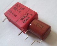
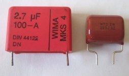
Wow these Panasonic MKP's !
How is it possible that Panasonic can make 450 V !! MKP's in such a small size ? Kemet & Wima's are so big , even in far less voltages than 450.
I got lucky ordering them in october , even then the in stock numbers were alarmingly low, now there are nearly none ! :
https://www.mouser.com/c/passive-co...capacitors/film-capacitors|~Voltage Rating DC(again : links don't show up)
And cheap , the ECWF(D) for a dollar , the ECWF(A) for nearly 2 . I don't see much difference between the 2 , just slightly different price and size.
The dimensions of the one I bought are even slightly less than the maximums advertised in datasheet and on Mouser. Luckily the markings are right , or I would think they gave me the wrong ones. I hope they are good , but aren't all MKP's good ?
The pics shows an MKT , but it is the same size for the 2,2uF MKP.
https://www.diyaudio.com/community/threads/polypropylene-capacitors.344009/page-6(I can't seem to make the link in the new forum software ?? )
A side note :
Wow these Panasonic MKP's !
How is it possible that Panasonic can make 450 V !! MKP's in such a small size ? Kemet & Wima's are so big , even in far less voltages than 450.
I got lucky ordering them in october , even then the in stock numbers were alarmingly low, now there are nearly none ! :
https://www.mouser.com/c/passive-co...capacitors/film-capacitors|~Voltage Rating DC(again : links don't show up)
And cheap , the ECWF(D) for a dollar , the ECWF(A) for nearly 2 . I don't see much difference between the 2 , just slightly different price and size.
The dimensions of the one I bought are even slightly less than the maximums advertised in datasheet and on Mouser. Luckily the markings are right , or I would think they gave me the wrong ones. I hope they are good , but aren't all MKP's good ?
The pics shows an MKT , but it is the same size for the 2,2uF MKP.
Attachments
Don't worry Markw4 , I'm not easily offended .No offense intended. Just wondering about your feelings on the subject.
Not really. I built a couple of LME49600 HPAs. Also, there was one in a Benchmark DAC-3 I once had. Also IIRC there is one in the Neurochrome HP-1 here. The various designs vary in SQ, with the HP-1 being my favorite of the bunch. In addition, there are some friends who have built IC buffer & opamp type HPAs. None of them has given me reason to prefer them over some particular discrete designs.
Aside from HP-1, I have been disappointed in IC HPA sound. However, I have also heard better-sounding-to-me discrete HPAs than any of the IC buffer designs I was able to compare. Of possible interest, there is a thread here in the forum on the standard HPA Stereophile uses for all headphone comparisons over the past few years. That particular discrete design also won multiple awards. I am not aware of any IC buffer design that compares to it in terms of SQ. In terms of AP measurements it would likely be a different matter. However, we have known for a long time that AP 'figure of merit' measurements do not completely predict SQ. Nothing new there.
The HPA I am thinking of is Pass HPA-1 (not to be confused with Whammy, a different design from Pass Labs). Someone here in the forum reverse engineered HPA-1 to produce a schematic and attached it to a post in the thread at: https://www.diyaudio.com/community/threads/pass-hpa-1-what-do-we-know.300060/
Some people built one and commented on the sound in the thread. Up to other people if they would rather do an IC buffer design for their own reasons. Nothing wrong with that. For myself, I would probably go with the HPA-1. Had one here on loan for several months, it was better than Neurochrome HP-1 in some ways. To me it sounded like Neurochrome HP-1 had a little lower distortion. Also sounded like Pass HPA-1 had the favorable characteristics that led Stereophile to choose it as their standard. It is very good, although I'm sure there will be better eventually.
I'm not sure why many here have a preference for discrete builds. For poweramps , I get it , but low power like an HPamp with excellent opamps and a buffer or paralled opamps as output , are easier . Why re-invent the wheel when engineers at T.I do it for me ?
I made the Elektor 1994 discrete HPamp , and it sounds ok , a little more "airy" than plugging directly in the CD player .
Seems like different people have different reasons for discrete HPA builds. There is only one reason that matters to me personally, which is how 'good' it can be in terms of what has proven hard to perfectly pin down, sound quality. IMHO in terms of today's science we are good a measuring figures of merit that have pretty good correlation with subjective sound quality, at least for most people. The correlation is not perfect though, so we are left with some degree of subjective opinion on what constitutes 'good.'
For now, until we have more complete science on human perception, people who want to know what 'better' sounds like will have to find a way on their own to listen and compare, then make their own judgements. Building at least one opamp & buffer HPA could be start. Building a Pass HPA-1 could be a great project too. Then at least there are two things to compare.
One reason I believe building an HPA-1 could be a 'great' project is because almost any good design isn't perfect and can be made to sound even 'better.' To get quickly approach the best we can do, it turns out starting with a really good sounding design can get you very close on the first pass. A very good discrete design has more degrees of freedom for further optimization than an IC design design does. Too much of an IC design is more or less cast in concrete.
Now, how to go about making a good design better and how to avoid fooling yourself in the process, are other subjects that could be talked about. Bottom line IME is they are problems that can be practically overcome with some time and effort.
Beyond that I would suggest to read the Stereophile review of Pass HPA-1, and some the other reviews and awards it earned. Its something a opamp & buffer design is not likely to be able to match. One reason why some people like HPA-1 is because of the high quality of the stereo illusion it can produce, even with headphones (and not because it has the lowest distortion figure of merit ever measured: it doesn't). Other reasons some people think it is special are described in some of the reviews.
Last edited:
You don't have to convince me to make the HPA-1 or other. I made my mind up , bought all the components , Susumu RG's , Panasonic MKP's, relays and of course the OPA828 and LME49600. I'm building it whether it sounds good or not , it's always a crapshoot just to rely on other peoples opinions about which opamp or discretes sound the best .
I just need some pointers for the PCB layout I'm about to make.
I used a simple test amp for a while :
https://www.diyaudio.com/community/threads/simple-hp-test-amp-questions.360797/To test the hardware around it , like Elvee's DeNoiser , 2 DC protectors , over and undervoltage detectors , delayed relais ,...
It all works well and sounded not bad , but that doesn't say much with the cheapo HP I'm using now.
What do you want to know about PCB layout? There are a lot of experienced people around here who can help, and there are some good application notes, good books, etc., out there. A well regarded and very practical book is: https://www.amazon.com/Electromagnetic-Compatibility-Engineering-Henry-Ott/dp/0470189304
I thought my questions about supply lines and groundplanes in post #15 were pretty clear.
Hard to rephrase them better.
# 21 about inductance of via's and if that matters for an HPamp.
Hard to rephrase them better.
# 21 about inductance of via's and if that matters for an HPamp.
A common concern with vias is that they can form a resonant circuit in combination with bypass caps. The resonant frequency depends both inductance and capacitance values. Whether or not it will ring if excited depends on the Q of the circuit. It is often recommended to use small X7R bypass caps since they add little inductance to via inductance, and they are somewhat lossy (high enough ESR) so that can provide some damping of ringing (reduction of Q).On T.I's SLOA068 pg 11 about decoupling high speed opamps , it shows that a 0,4 mm via through a 1,5 mm PCB has an inductance of 1,1nH . My via's are much wider , and longer if I use 2 x 1,5mm PBC , which boosts the nH's .
At what number of nH does that start playing a role in audio circuits , or can it make high speed opamps less stable when decoupling through such via's?
Actual ringing should not occur in a passive LC circuit unless something forcing function excites it. Sometimes that can happen for unexpected reasons, such as RFI/EMI incursion into an otherwise wideband circuit intended for audio.
One way to possibly help mitigate the tendency towards ringing is to avoid vias in the bypass cap transient current path. For example, if the bypass cap current flows primarily in the top layer of a PCB without passing through any vias along the way, then ringing might not appear differentially across an IC power and or ground pins. That is not to say that all possible problems would necessarily be mitigated by such a strategy.
IIRC in Ott's book, a via/bypass cap resonance example occurred at 50MHz. Again IIRC, it was found to be hard to raise resonance a lot above that while still providing sufficient bypassing. Turns out primary signal path circuitry often works fine anyway. Also, there is some further information out on the net about that whole subject. Some of it is newer than Ott, so it might be worth looking around for if there is a concern.
Regarding audio circuits, some people feel that X7R bypass cap nonlinearity can have an adverse audible effect on SQ. In such cases it may be possible to use more linear caps such as C0G/NPO or perhaps SMD film types. Since such caps tend not to be inherently lossy, a linear series resistor may needed to be added to control damping. Since net inductance can be increased using physical larger caps and separate series resistors, self resonant frequency of the bypass circuit may be forced lower than if using X7R caps. However, that may not especially matter if excessively wide bandwidth circuitry is not used for audio circuits. Observation of prototype circuit decoupling waveforms with a low capacitance active scope probe might be useful.
Again, further information is available in various books and articles. I will let somebody else start on the grounding and power question.
Via's will be in the transient current path , but the caps will be tantalum not X7R's .One way to possibly help mitigate the tendency towards ringing is to avoid vias in the bypass cap transient current path. For example, if the bypass cap current flows primarily in the top layer of a PCB without passing through any vias along the way, then ringing might not appear differentially across an IC power and or ground pins. That is not to say that all possible problems would necessarily be mitigated by such a strategy.
The layout example in OPA 828 (and other opamps) datasheet also shows via's going to the bypass caps.
But do 10's of nH matter with lower frequency current peaks like in audio , if the circuit is in a well shielded casing so RFI/EMI stay out ?
Page 32 of OPA828 datasheet (Section 10, Layout Guidelines) states: "Connect low-ESR, 0.1-µF ceramic bypass capacitors between each supply pin and ground, placed as close as possible to the device"
Is there some reason why that can't or shouldn't be done?
Is there some reason why that can't or shouldn't be done?
Since this is sound replaying system, better sound means more closely resembling the original, not what you or someone like better.For now, until we have more complete science on human perception, people who want to know what 'better' sounds like will have to find a way
That would be a self-fi, not hi-fi.on their own to listen and compare, then make their own judgements.
Their measurements help to some degrees but the rest of subjective listening impressions don't mean anything to the readers unless they were there in that room on that day. It's good for the marketing though. 😒Beyond that I would suggest to read the Stereophile review of
Learn some kind of layout software, there are so many tutorials out there. Your problem with EasyEDA might have simply been that you did not place "not connected" flags on the unused pins of OPA828, but you can click away the warning that pops up. Also, what are you trying to build exactly? Two channels on one PCB? No gain selection, no volume control potentiometer, no protection circuitry? Just a headphone driver stage?
It can and will be done , but not without via's . Like I said before : the signal on the smd side of the PCB , the supply and ground on the other side. With Elvee's DeNoiser , I can't use low-ESR ceramics , so a tantalum will have to do.Page 32 of OPA828 datasheet (Section 10, Layout Guidelines) states: "Connect low-ESR, 0.1-µF ceramic bypass capacitors between each supply pin and ground, placed as close as possible to the device"
Is there some reason why that can't or shouldn't be done?
How many of us are able to listen to the original ? It's not like we're in the recording studio where they made it , or even at a live concert.Since this is sound replaying system, better sound means more closely resembling the original, not what you or someone like better.
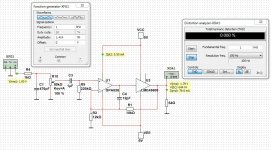
I couldn't even find the OPA828 in their libraries , I think I made a test with a TL07x .Learn some kind of layout software, there are so many tutorials out there. Your problem with EasyEDA might have simply been that you did not place "not connected" flags on the unused pins of OPA828, but you can click away the warning that pops up. Also, what are you trying to build exactly? Two channels on one PCB? No gain selection, no volume control potentiometer, no protection circuitry? Just a headphone driver stage?
And again : is the layout that the software uses ideal ? For just linking components I don't need software , it's for doing it as good as possible.
I build differently than software and folks here do. I use TTH as SMD when needed. The LME will be used through the epoxy board . No way to simulate that in software where I can't even make regular designs work.
Does it matter whether the 2 channels are on one PCB or 2 seperate ? Both have their own supply lines.
Look at "the wire" : no gain selection, no volume control potentiometer, no protection circuitry . Again like I wrote before , mine has protection , and no gain controle needed.
It's like "the wire" , but with input cap , relay output and V & DC protection.
It will be used for computer and music player that have their own volume control . Maybe even used to replace the HPamp in my preAmp , which already has volume control.
Not many at all. That's why you want DAC and amp with flat frequency response and distortion level below audible threshold so that those will process / amplify per the industry standard. Once you get that taken care of, you don't need to worry about those components. Fortunately for the audio electronics consumers, DACs and amps meeting that standard are cheap these days. Same goes for the cables. What you do need to worry about is the speakers and room acoustics because that's where the bottle neck of sound reproduction is.How many of us are able to listen to the original ? It's not like we're in the recording studio where they made it , or even at a live concert.
- Home
- Amplifiers
- Headphone Systems
- Anyone make OPA828 - LME49600 combination