Please don't become another victim of adding an R into Vituix.
Thanks and hopefully I won't in the future now it has been pointed out.
Wine might be an option if the full virtual machine isn't simple
https://kimmosaunisto.net/Software/VituixCAD/VituixCAD_in_Linux_v0.1.pdf
https://kimmosaunisto.net/Software/VituixCAD/VituixCAD_in_Linux_v0.1.pdf
I have also used VC under WINE. The fonts were not the best, too small and symbols were missing.. but it worked.Wine might be an option if the full virtual machine isn't simple
Guys -- do you want to design a loudspeaker, or do you want to discuss software packages and how to run them?
These where Beweridge SW2.
Column electrostatics with acoustic lense and likely more besides? Not an option in my current room but interesting nonetheless.
What kind of stuff you guys plan to simulate with the BEM? response at listening spot with all walls/floor/ceiling in? or just the effect of front wall to some random observation point? Or just modelling a construct and then simulating acoustic output of that? All of these?
Fluid, andy, how much error there is just by using simplified VituixCAD sims in comparison to more elaborate BEM sims and is it meaningful in grand scheme of things, curtains and all mentioned earlier? I'm thinking with the whole concept in mind.
I believe BEM could help optimize some shapes and aspects later on with the project. Sub systems that live in detail would benefit the detail most. But isn't the whole shebang impossible to model accurately making more simpler generalized approach more effective? Can we find out what the error is between 3D room BEM and the simplified one corner in room estimate in VCAD?
I have no experience on BEM, and haven't learned CAD yet either so I probably don't have good idea what the usability, limitations and possibilities are. I'm glad you guys can utilize and demonstrate some of the possibilities 🙂
Last edited:
Guys -- do you want to design a loudspeaker, or do you want to discuss software packages and how to run them?
Patience young grasshopper. If the design is to evolve based on an evidence-based group discussion we will first need to sort out methods to generate the evidence. In a few days I should have a method to generate a set of simulations to quantify the strength of the on-wall effect and the relative performance of the 3 ways to address it mentioned above. No doubt the work flow will be discussed and alternatives proposed but we will also be in a position to push the design forward a stage.
After that of course we will need to size the drivers and that would best be done with some way to simulate the level of non-linear distortion particularly if we lean towards a cardioid radiation pattern which tends to push things in this respect. That may need another pause while software is found or pulled together. Or it might not if there is enough confidence in rough estimates extrapolated from measurements to take the relevant design decisions. We will see.
None of the 3 methods really deal with higher frequencies (partly anyway). Your edge treatments will be critical there.
My take where not so much about electrostatics and lenses than rather just considering a design that would to be optimised for side walls. I have used side wall positioning of speakers and I find that not steering at a pair of speakers is adding to the experiance.
//
//
Let's not forget some amount of sidewall reflections are needed for envelopment, etc. If you get too directive, you will need ambience drivers. I've been able to get quite impressive (simulated) directivity in Vituix using cardioid - >-15 db to the rear but only about -6 db to the sides but impressive as it may be, it still just moderates the boundary interference but a lot of research suggests that is all it needs to do.
What kind of stuff you guys plan to simulate with the BEM? response at listening spot with all walls/floor/ceiling in? or just the effect of front wall to some random observation point? Or just modelling a construct and then simulating acoustic output of that? All of these?
Fluid, andy, how much error there is just by using simplified VituixCAD sims in comparison to more elaborate BEM sims and is it meaningful in grand scheme of things, curtains and all mentioned earlier? I'm thinking with the whole concept in mind.
I believe BEM could help optimize some shapes and aspects later on with the project. Sub systems that live in detail would benefit the detail most. But isn't the whole shebang impossible to model accurately making more simpler generalized approach more effective?
I have no experience on BEM, and haven't learned CAD yet either so I probably don't have good idea what the usability, limitations and possibilities are.
My hope is to try to use the project to explore how much of the way a design project like this would be performed today in the engineering industry. Of course we don't have access to the expensive commercial software tools like COMSOL or many of the expensive manufacturing techniques. However there is free research software around with most of the capabilities of software like COMSOL but in a less reliable and easy to use form. Speaker DIY folk haven't used this software in the past and so expect progress to be slow and frustrating. Manufacturing techniques like rapid prototyping and numerical controlled machines are becoming cheap enough to use by hobbyist and so we can look to include curved surfaces in the design both for waveguides around drivers and the external shape of the speaker. This requires reasonable 3D acoustic software to create a reasonably optimised design.
How many others are interested in pushing the design boundaries a bit for speaker DIY remains to be seen. Many with a more "practical" leaning have no interest at all in this sort of thing. Nor should they if they don't find it fun.
None of the 3 methods really deal with higher frequencies (partly anyway). Your edge treatments will be critical there.
The higher frequencies will need handling in the same way as a speaker out in the room. The reason to sort out how to handle the close presence of the front wall first is because it changes the whole configuration of the speaker. Once the configuration is known how to size the drivers for the higher frequencies and control their radiation pattern can be tackled. I would hope to use BEM for this as well in order to shape waveguides and the front of the speaker.
^ Andy, can't we reason that from simple model pretty nicely, and make some rough estimates what is needed to reduce effect of front wall?
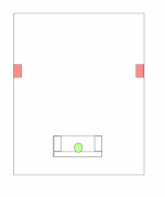
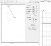
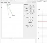
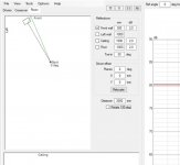
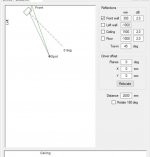
First 4 attachments are speaker toe in from 0 to 45 in relation to front wall first reflection point to the listening spot with 60-60-60 stereo listening triangle. From the attachments we see the line to first reflection point is roughly ~160-90 degrees, depending on the toe in, depth of the speaker and listening distance and what not. These angles we want to manage one way or another, simplified it is the back quadrant we need the attenuation for reduce the reflection. And it looks like something like ~130 degrees would be perhaps on the middle of this range, so lets use that in the example.
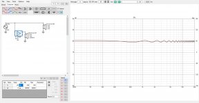
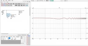
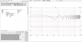
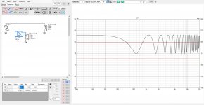
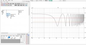
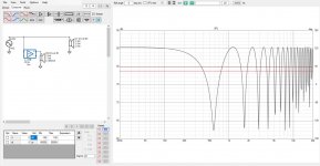
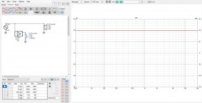
How much to reduce sound from the reflection? Why? The reflection from the front wall will superimpose to direct sound at listening spot. Next attachments are a simple test how much attenuation for the secondary sound source is required to reduce the interference pattern that emerges when the two sounds combine.
One could get more accurate graphs with BEM but is there more info gained so that we can estimate what kind of system structure would provide sufficient attenuation at any particular frequency to the front wall? Yes and no. Because, as it looks like we have to attenuate the reflection ~20db to get the interference below +-1dB. Anything less attenuation and the interference gets bigger. Without any attenuation at all there is ~6db of constructive interference and perhaps similar amount or more of destructive interference in reality, so roughly +-6db.
For nice sound I've seen on the internet that something like +-1 db target for loudspeaker measured response is considered very good, many can't do +-3dB. If we reflect to this we would likely want to have as much attenuation to front wall as we possibly can for the bandwidth that suffers the destructive interference, eg. wavelenghts shorter than distance from the source to wall, to have as good sound as possible.
If you look at what the wavelengths are, on the simple tests 30cm distance from wall the interference happens > 400Hz. From this we can now reason it is not possible to use waveguide alone, since sufficient pattern control down to 400Hz would make very big device. Last attachment is measurements of my ~20cm square waveguide with 90 degrees nominal pattern. From this it looks like ~20db attenuation is achieved to angles past 90 degrees so this would be enough, but it is only roughly above 2kHz where the waveguide still has proper control of the sound. Can't extend the pattern control down to 400Hz without greatly increasing the size of the device and thus distance from the wall which in turn would mean the interference to start even lower in frequency and we'd be chasing our own tail. Reasoning from this we need physically small device that can do attenuation to back quadrant and this is the cardioidish variety. Cardioidish from the frequency up that depends on distance to front wall. Cardioidish can do 2 octaves with ease, 3 with reduced SPL capability so it has to be waveguide above that, or another cardioid.
It is just matter of doing as good cardioidish design with max attenuation to Design angle (towards reflection point) to achieve least interference due to the front wall. You could use BEM to come into same or similar concept, to find out what kind of system works near wall for minimal effect / interference to overall sound 😀 I'm not sure if we need more info than this? to be able to select suitable options for over all concept? If you can think of some other concept then you could model it and verify by BEM, but I'm not sure what that would be? Peace
Since the project is not much defined yet we cannot rule out big waveguides, or very thin speakers etc. This is just one possible system.
First 4 attachments are speaker toe in from 0 to 45 in relation to front wall first reflection point to the listening spot with 60-60-60 stereo listening triangle. From the attachments we see the line to first reflection point is roughly ~160-90 degrees, depending on the toe in, depth of the speaker and listening distance and what not. These angles we want to manage one way or another, simplified it is the back quadrant we need the attenuation for reduce the reflection. And it looks like something like ~130 degrees would be perhaps on the middle of this range, so lets use that in the example.
How much to reduce sound from the reflection? Why? The reflection from the front wall will superimpose to direct sound at listening spot. Next attachments are a simple test how much attenuation for the secondary sound source is required to reduce the interference pattern that emerges when the two sounds combine.
One could get more accurate graphs with BEM but is there more info gained so that we can estimate what kind of system structure would provide sufficient attenuation at any particular frequency to the front wall? Yes and no. Because, as it looks like we have to attenuate the reflection ~20db to get the interference below +-1dB. Anything less attenuation and the interference gets bigger. Without any attenuation at all there is ~6db of constructive interference and perhaps similar amount or more of destructive interference in reality, so roughly +-6db.
For nice sound I've seen on the internet that something like +-1 db target for loudspeaker measured response is considered very good, many can't do +-3dB. If we reflect to this we would likely want to have as much attenuation to front wall as we possibly can for the bandwidth that suffers the destructive interference, eg. wavelenghts shorter than distance from the source to wall, to have as good sound as possible.
If you look at what the wavelengths are, on the simple tests 30cm distance from wall the interference happens > 400Hz. From this we can now reason it is not possible to use waveguide alone, since sufficient pattern control down to 400Hz would make very big device. Last attachment is measurements of my ~20cm square waveguide with 90 degrees nominal pattern. From this it looks like ~20db attenuation is achieved to angles past 90 degrees so this would be enough, but it is only roughly above 2kHz where the waveguide still has proper control of the sound. Can't extend the pattern control down to 400Hz without greatly increasing the size of the device and thus distance from the wall which in turn would mean the interference to start even lower in frequency and we'd be chasing our own tail. Reasoning from this we need physically small device that can do attenuation to back quadrant and this is the cardioidish variety. Cardioidish from the frequency up that depends on distance to front wall. Cardioidish can do 2 octaves with ease, 3 with reduced SPL capability so it has to be waveguide above that, or another cardioid.
It is just matter of doing as good cardioidish design with max attenuation to Design angle (towards reflection point) to achieve least interference due to the front wall. You could use BEM to come into same or similar concept, to find out what kind of system works near wall for minimal effect / interference to overall sound 😀 I'm not sure if we need more info than this? to be able to select suitable options for over all concept? If you can think of some other concept then you could model it and verify by BEM, but I'm not sure what that would be? Peace
Since the project is not much defined yet we cannot rule out big waveguides, or very thin speakers etc. This is just one possible system.
Attachments
-
 0-toe-in-60-listening-window.jpg58.7 KB · Views: 96
 -
 10-toe-in-60-listeing-triangle.jpg59.9 KB · Views: 89
 -
 30-toe-in-60-listeing-triangle.jpg66.5 KB · Views: 89
 -
 45-toe-in-60-listening-triangle.jpg37.2 KB · Views: 86
 -
 -25db.jpg177.4 KB · Views: 89
 -
 -20db.jpg178.5 KB · Views: 93
 -
 -10db.jpg180.4 KB · Views: 81
 -
 -6db.jpg225.3 KB · Views: 80
 -
 -3db.jpg224.1 KB · Views: 76
 -
 another-ideal-30cm-back.jpg201.5 KB · Views: 76
 -
 ideal-alone.jpg181.2 KB · Views: 90
 -
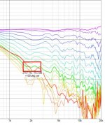 wg.jpg98.6 KB · Views: 100
Last edited:
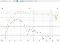
Here is simulation from measurements showing frequency response to 130 degrees and listening window. Sound to the front wall is roughly ~15db or more down in comparison to direct sound. This is 20cm waveguide, 8" cardioidish mid, flat bass. I'm not sure why the bass is attenuated here, it is wide baffle though and full space simulation. Anyway, it looks like the cardioid + waveguide can have -10db or more attenuation to front wall, which would make the interference at listening spot +-3db or less.
Attachments
@tmuikku, do you see how the reflection is drawn through the middle of the cabinet from the driver..
VC makes a good guiding tool for speaker placement. You get these results from traditional techniques.
However there is a frequency dependent diffraction component which needs to be considered for an on-wall design, which VituixCad is not suited for.
VC makes a good guiding tool for speaker placement. You get these results from traditional techniques.
However there is a frequency dependent diffraction component which needs to be considered for an on-wall design, which VituixCad is not suited for.
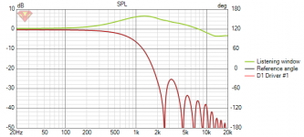
Yes, hence estimate off 90-160 degrees of axis depending how the system is implemented, where the reflection happens. Reflection angle can be found out more specifically, but the system could be adjustable and thus change. Hence back quadrant. Diffraction we would like to minimize anyway, that is just part of any loudspeaker design in my opinion. Unless maximum sound quality is not the most important objective. Attached is ideal 8" driver on a very smallest possible baffle, showing response to 130 degrees and the listening window. As you see there is only frequencies that are relatively long to the baffle size, the ones that you see with bafflestep, to the 130 degrees and anything above is just beaming and making interference. And you would not want to crossover any higher in any case, in any conventional speaker design close to wall or not. So I don't see what you mean with frequency dependent diffraction component being somehow different here? Do you mean if there was sufficiently small transducers so that the construct would be very close to the wall, like within few centimeters instead of tens centimeters?
Anyway, I found it rather hard to steer max attenuation of cardioidish to the 130 degree territory. Cardioid is the easiest (max attenuation ~180 degrees), hyper and super cardioidish more difficult but not impossible. I'm not ruling out other solutions, I just haven't been able to figure out what those might be given the premise we have some kind of physical object close to wall, not inside the wall, while considering diffraction and polars and what not, basics of good loudspeaker.
Anyway, I found it rather hard to steer max attenuation of cardioidish to the 130 degree territory. Cardioid is the easiest (max attenuation ~180 degrees), hyper and super cardioidish more difficult but not impossible. I'm not ruling out other solutions, I just haven't been able to figure out what those might be given the premise we have some kind of physical object close to wall, not inside the wall, while considering diffraction and polars and what not, basics of good loudspeaker.
Attachments
Last edited:
BEM or traditional analysis is important because diffraction behaviour around the wall is a critical issue. VituixCad does not do that part of speaker design.Diffraction we would like to minimize anyway, that is just part of any loudspeaker design in my opinion.
It’s also useful to recognise that a cardioid response in the low-frequency region is limited by the fact the speaker is going to be ‘on’ the wall. I haven’t tried this in VituixCAD myself, but using a side porting method like the Dutch&Dutch 8C or the passive cardioid rear ports of the Fulcrum Acoustic stuff might be trickier to verify without a numerical solution.
Analytical and numerical methods all have their place.
Analytical and numerical methods all have their place.
- Home
- Loudspeakers
- Multi-Way
- High Fidelity On Wall Speaker Group Project