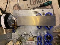
Couldn’t resist the ground plane idea. Hand cut, filed, and ready for drilling. Maybe make a trace in the middle from first to second set of caps, but will try like this first.
0v take off at the back, in the middle, geometrically far from the currents between halves. Excited. Sloow, steady.
0v take off at the back, in the middle, geometrically far from the currents between halves. Excited. Sloow, steady.
Attachments
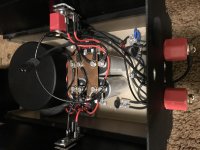
This is how I did mine years ago. Juma's cap multiplier circuit. Red insulator on the side is the main star ground. Picture is kind of a sneak peek of my SissySIT rework, binding post delete, coupling cap upgrade, and some other small tweaks I've been meaning to do for awhile...
Attachments
Last edited:
Hello,
I'm posting my question here because I can't find appropriate threads, I have nichicon 10kuF /50V capacitors, I measured them, they have capacitance within the stated parameters and an ESR between 1 and 1.8 Ohm.
The Datasheet does not show the typical ESR parameters for the capacitor. In your opinion, is the ESR within the acceptable range?
Thank you for your answers.
Hello,
I'm posting my question here because I can't find appropriate threads, I have nichicon 10kuF /50V capacitors, I measured them, they have capacitance within the stated parameters and an ESR between 1 and 1.8 Ohm.
The Datasheet does not show the typical ESR parameters for the capacitor. In your opinion, is the ESR within the acceptable range?
Thank you for your answers.
What did you use to measure them? Can you post the part number of that capacitance meter?
The capacitor in question is this one.
LLS1H103MELC Nichicon | Mouser
10 000 uF 50V, spec sheet gives tan (delta) as 0.30 max.
To calculate ESR:
Calculating capacitor ESR from Tan(δ) - Tech Tips - Engineering and Component Solution Forum - TechForum │ Digi-Key
ESR = tan (delta)/(2 x pi x f x C)
tan (delta) = 0.30
pi = 3.14159
f = 120 Hz
C = 0.010 F
Calculated ESR = 0.040 Ohm

The large measured ESR value could be the result of measurement errors that may be related to how the contact, or interface to the capacitor, was made.
The measured value of some 1-2 ohms is waaaay too high. Due to I2R, the generated heat will be quite high, especially when the capacitor is used in high current applications, like... Aleph J, where the heat increase will be proportional to the squared increase of current.
The measured value of some 1-2 ohms is waaaay too high. Due to I2R, the generated heat will be quite high, especially when the capacitor is used in high current applications, like... Aleph J
, where the heat increase will be proportional to the squared increase of current.10 000 uF 50V, spec sheet gives tan (delta) as 0.30 max.
To calculate ESR:
Calculating capacitor ESR from Tan(δ) - Tech Tips - Engineering and Component Solution Forum - TechForum │ Digi-Key
ESR = tan (delta)/(2 x pi x f x C)
tan (delta) = 0.30
pi = 3.14159
f = 120 Hz
C = 0.010 F
Calculated ESR = 0.040 Ohm
The electrolyte’s temperature-dependent conductivity is a major contributor to ESR; your calculations should be ignored as irrelevant.
Balanced or SE inputs
I'm in the early planning stages of my Aleph J build and would like to incorporate the option to use balanced or single ended inputs. I may also think about making a pair of mono blocks rather than a stereo amp in a single chassis. But back to the balanced/SE inputs; from reading through this thread (and many many others) it looks like a fairly easy configuration to implement. If I've missed something simple, obvious or plainly damn right stupid in my thinking and the attached sketch, please point me in the right direction.
Many thanks,
Gary
Attachments
The electrolyte’s temperature-dependent conductivity is a major contributor to ESR; your calculations should be ignored as irrelevant.
The calculation was for 20 degrees C, not for in-service condition.
tricksters was questioning his ESR measurement which was at room temperature. I was just providing a calculated ESR based on specifications for comparison since he was wondering what the specified ESR was.
I was just trying to help out a fellow diyer.
I'm in the early planning stages of my Aleph J build and would like to incorporate the option to use balanced or single ended inputs. I may also think about making a pair of mono blocks rather than a stereo amp in a single chassis. But back to the balanced/SE inputs; from reading through this thread (and many many others) it looks like a fairly easy configuration to implement. If I've missed something simple, obvious or plainly damn right stupid in my thinking and the attached sketch, please point me in the right direction.
Many thanks,
Gary
That will work, but you are introducing an additional, undesired capacitance, inductance and relay contact resistance in the (what should be a direct) input signal path. So, don't do it.
Balanced input, remove the short circuit protection transistor and associate resistors, remove the C1, optimise the common signal returns & grounding, minimise the internal wiring lengths... and stay tuned to be completely and utterly blown away.
... and also, Aleph J does not have any local decoupling of DC rails on amp PCB... It pays to investigate how to lower the supply rail impedance at higher frequencies as well; how to bypass those large capacitors with smaller values, and maybe use some film capacitors as well.
Last edited:
- Home
- Amplifiers
- Pass Labs
- Aleph J illustrated build guide