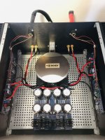
Since it is PSU day today, here is one DC section of my PSU prototype finished, sans chassis gnd/loop breaker.
Ripple is not my concern. Exciting stuff will be whether loops are under control. We will see. Intention was for 0v tapping section to be even further from the equalizing currents between last two caps, but other stuff dictated the distance. If noisy I just have to make a new ground plane, simple as that.
Also, due to same circumstances, bridge wires are a bit long. Maybe I’ll shorten later.
Anyways, for prototype, pretty happy.
After gnd is connected I will test under load. Excited about ripple, modelled to very low, lets see what the real world says. Also possible loop areas as well as inductors in line (but not imminently close) to amp circuitry. We will see 🙂
Quite a lot of gear stuffed into that space, kinda excited it all fits nicely.
Edit: been in the making inside my head for 7 months, so quite rewarding to finally see it. Will it work the wonders i hope? Maybe. If not, this is an excellent opportunity to learn and perfect. And if it’s not perfect first time around? Who the heck cares. I did this.
Regards
Andy
This looks awesome, can’t wait to see the finished amp.
I have been asked before, and again recently, for some pointers in support of what I've been saying here... so, here are the photos.
The layout shown will ensure the absolute minimum length of all wiring. AC wiring is probably 15cm long max, from the IEC connector to the transformer (including the NTC). It is also tucked underneath the transformer plate. I do not believe in terminal blocks, i.e. in screw contacts (in contacts - period). Hence, the mains NTC is mounted/soldered on the IEC connector itself.
The DC wiring is also minimised by properly orienting the PS PCB, so that the DC connectors are right in the middle of the AMP PCB's.
The common point of the PS PCB is wired to chassis via a think and short multi-strand wire (one place where a solid core wire is NOT desirable)- no NTC here. This is me thinking RF noise here. Using NTC with long thin legs will work for DC, but will do nothing when it comes to coupling the PS PCB ground noise to chassis - especially for a higher frequency noise.
The speaker common is routed back to the common of the PS PCB.
I also removed the overload protection transistor and the C1 capacitor (which was bypassed with a wire link).
The ground return points on that PS PCB are not interchangeable. It pays a lot to properly wire the returns back to a common of the PS PCB. This could mean that you do not really need two power supplies (which automatically fixes the problems of bad common returns). It's also worth noting that I have links between two PS PCB's commons, soldered only in one place.
Each step mentioned above, either implemented from the start or modified later, contributed a lot to the final result, which is absolutely amazing. I can hear clearly depth perception in my soundscape, a completely natural presentation that works amazingly well with my May DAC in NOS, great space - but at the same time the distinctive focus of individual instruments/voices... and fantastic low-end extension and grip (I have 4-ohm speakers).
So, there you go, take it or leave it.... at least give it a go because this is supposed to be a tinkering DIY exercise... and you just may like the result. If not, go back to what you believe worked/works best for you.
Attachments
Great post, Boky. Thank you! I have tinkered a lot with the grounding scheme of the stores PCB, and conclusion is the same as yours: it makes a notable difference. I have not tried dropping the NTC between audio and safety gnd though. I did solder the junction exactly the same way as you.
I also mounted the «soft start» NTC directly at the IEC first time around, and that worked pretty well. What I have not tried, yet, is the layout you use with tranny first and PS in the middle/towards the front, which gives some nice advantages. I would think with a potted shielded tranny, that is the way to go. I do not have a potted tranny, and also there are two, so I chose Mightys/Chedes way of mounting them. I am still considering getting the last set of caps more towards the middle, which will mean a major mod.
Another alternative is using some PCBs (no copper) that I bought, and merely glue the caps on there to save space and reduce loop areas, and save a lot of space. Maybe putting the inductors under them, extending their wires. That would achieve short DC wires.
I am ready to tinker. Thought is to use the protoype with full gnd plane first, see where it leads me, and work on from there. I have considered several beta versions, but in the end decided for this solution as a starting point.
Alternatives mainly consist of adjusting the gnd plane in several ways, for example cutting a trace from the first set of caps to next or last set, to control equalizing currents. Also considered is pure wire all the way, minimizing loop areas but making it a bit more challenging to tap the 0v from anywhere but one of the load points at the last set of caps. T’ing off, reference to hifisonix, is more challenging with such a solution.
Anothet alternative, considered up until yesterday, is to make a small triangle ground plane at the last set of caps, using wires everywhere else (ref one of Mightys builds).
The current solution has the advantage of simplicity (less wires) and pure look. So let’s see where it leads.
Tinkering is fun, I take your guidance with me.
Building a P2P is a great learning process. But it is not the easiest way, for bloody sure
Regards,
Andy
Last edited:
This looks awesome, can’t wait to see the finished amp.
Thank you! Btw, if you choose to mount your trannies like Mighty suggests, there are some photos in a few posts from august/september (I think) that shows how Mighty and I did it. I can take a few closeups too. The plates used are actually completely flat, from a hardware store. Angles are hammered in 🙂 There is room in between (at the very front) for either Mightys NTC board or some other connection solution, or you could just solder the NTC’s at the IEC and wite the trannies directly from there, like Boky suggests.
OK, heat is that much that NTC will melt IEC in few decades or so, but it makes me cringe even thinking of soldering it directly to IEC
ZM's OCD or what, but cringing is it

ZM's OCD or what, but cringing is it
Another configuration that I've used is to mount the transformers vertically at the front and mount the CRC on the chassis floor.
Since you have a 5U/400, space is not likely an issue, but for tighter amps and/or amps with amps that have signal transformers, I've found that to be the configuration that results in the lowest noise (for me). You've purchased the covers for your donuts, have smaller/shielded (AS) donuts, and already will have them at the front, so... 6 of one; half/dozen of the other. Pick what results in shortest / cleanest AC wiring.
Also, you didn't ask, but ... I did find that running my mains wiring between the bottom panel and the perforated plate had a measurable difference in noise as opposed to running it above the plate. See multiple posts for recommendations re: twisting etc. Ben Mah, has a meticulous process for lowering noise and a very nice write up on how to achieve it.
tl;dr - Since you're going with monolithic rectifiers and using a big chassis, you likely will never need the space, and you likely will never have an issue with noise with the AJ, but it's never a bad idea to lay things out as cleanly as you can.
...
Also, you didn't ask, but ... I did find that running my mains wiring between the bottom panel and the perforated plate had a measurable difference in noise as opposed to running it above the plate. See multiple posts for recommendations re: twisting etc. Ben Mah, has a meticulous process for lowering noise and a very nice write up on how to achieve it.
...
exactly why I'm repetitively writing - base plate lip up, put 10mm risers for base plate, move all mains wiring beneath
I'm just using longer M4 screws (than sent by Modushop) and risers are nothing else than stack of 4-5pcs of M5 nuts
one thing more - I'm putting split washer with every screw in case, except those for bottom and top cover, of course
if I could find nice black ribbed washers for these, I would use them here too
one thing more - I'm putting split washer with every screw in case, except those for bottom and top cover, of course
if I could find nice black ribbed washers for these, I would use them here too
Last edited:
Hey🙂
What do you all think/say/know about the IEC inlets with filtering?
Is it any sonic benefits with them compared to the standard plastic type with the simple safety cap filtering?
What brand/type is in that case the recommended brand/size/type for an Aleph J?
IEC mains noise filter teardown and explanation - Schaffner FN261S-6-06-10 - YouTube
simple as that - go and see ( 6moons, any other site showing pics with cover off) are there any in comparable FW and PL products
I know the answer on that, but don't want to rip you of pleasure of greening, when you find your own conclusion
I know the answer on that, but don't want to rip you of pleasure of greening, when you find your own conclusion
 :
: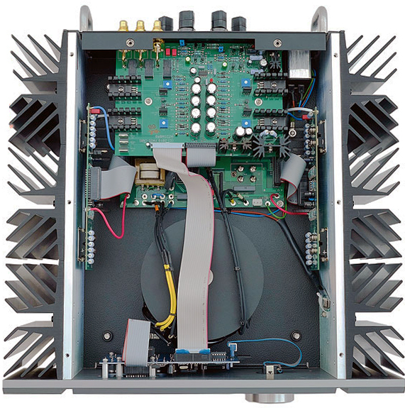
Well thats a beautiful Pass Labs build. And they are using the IEC filtered inlet.
But. It is probably hard to quantify the possible sonic benefits...
I have been doing the HiFi- thing for a very, very long time, but i am brand new at this wonderful amplifier building thing 🙂
I figure i will resume building them with the standard AC- inlets, and then a beautiful day upgrade one of the Aleph J:s with a filtered IEC, and do some A-B testing 🙂

- Home
- Amplifiers
- Pass Labs
- Aleph J illustrated build guide