That 1:6 means also 1:6 in voltage output.
You now have 1:4 in the Riaa stage, make it 1:6.
Fix the collector resistances at 200 and the diff to se stage to 1x, in line with what Syn08 also advised earlier and you are done.
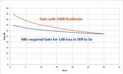
I’ll send you again the previous graph with the minimal gain required but now also added with the gain you will get with fixed 200R resistors.
My expectation is that they will be almost identicical, meaning that there is no need for different collector resistances.
Hans
You now have 1:4 in the Riaa stage, make it 1:6.
Fix the collector resistances at 200 and the diff to se stage to 1x, in line with what Syn08 also advised earlier and you are done.
I’ll send you again the previous graph with the minimal gain required but now also added with the gain you will get with fixed 200R resistors.
My expectation is that they will be almost identicical, meaning that there is no need for different collector resistances.
Hans
I found that with 20R Carts and above, noise penalty of the Diff to SE becomes too big because the min required gain for 1dB noise penalty cannot be achieved.
That's why your original two amp solution with 100uF in front are the better solution.
This has taken some time to compare all options, so within an hour I will come back with the results.
Hans
That's why your original two amp solution with 100uF in front are the better solution.
This has taken some time to compare all options, so within an hour I will come back with the results.
Hans
The dual amp version with two 100uF caps, add 4.33nV/rtHz to Vx,Vy instead of the 8.88nV/rtHz of the single amp version.
This made it possible to reduce Gain of the first stage by 6dB to meet the max 1dB noise addition to the first stage, and Carts above 20R now fall within the 1dB.
See outcome in image below.
In the previous version, Rcol could go to 250R, but with the 1k from the Diff to Se converter attached to it, it became effectively 200R.
The other current leaking effect was that the collector voltages came exactly in the middle of the max voltage swing with 5.2Volt.
However the dual opamp Diff to Se converter is not DC coupled, causing a shift from the collector voltages.
To bring them back to 5.2Volt, 294R resistors are needed and to get the previous effective 200R load two resistors of 625R are connected to gnd after the caps.
Now gain is as before with 250R//1K resistors and the min required Gain for a 30R Cart meets exactly the real Gain.
Gain for low R Carts could optionally be reduced with a single resistor between the two collectors.
Hans
.
Attachments

Last edited:
In the above graph with min Gain, it is easy to see how much gain can be dropped to still meet the 1dB criterium.
For an 1R cart this could be 9.9dB, for a 6R cart 6.1dB and for a 10R cart 4.4dB.
So up to 6R a factor 2 seems reasonable, translating in one 400R resistor between the collectors.
Just for fun I spent some time on your project, but I have involved myself already too much in someone else's design, so for the moment I will pull back.
Hans
Hans, here is the spread sheet - hopefully no major errors.
This looks at the output voltage of the head amp with a fixed 200 Ohm (you can set it to whatever you like in the SS) and with the optimized load (to give c. 2.5mV at each collector so 5mV differentially) across the collectors.
The spot and integrated noise floor is also calculated.
Please take a look.
NB My spread sheet has not included diff amp noise - its only noise at Vx, Vy
Attachments
Last edited:
Bonsai,
I need a bit more time to look at your spreadsheet, but I see a few things that need further attention.
Hans
I need a bit more time to look at your spreadsheet, but I see a few things that need further attention.
Hans
Hans, here is the spread sheet - hopefully no major errors.
Haven't checked, but I can tell you are making your life more complicated than it could be.
The noise of any current source is SQRT(2*q*I*deltaF), no need to convert voltage to noise.
Hans,
maybe easier to go with the dual opamp diff amp, use 220 Ohm f/back resistors and then 2.2uF DC blocking with 47k opamp input bias resistors. No noise penalty over the 100uF approach.
Switching the collector resistors to optimise the load is easy and cheap enough - but probably only 3 steps needed -50, 100 and 200
Is this the input source you are referring to here ie Vcart/Rcart ?
Everywhere, including the bipolar input current noise (which is simply the noise of the collector bias current, divided by Beta). For bipolars it is usually easier to handle all the noise calculations in terms of noise current instead of voltage noise.
But this could be just me, finding it simpler this way... the end to end results should be identical, anyway.
"For bipolars it is usually easier to handle all the noise calculations in terms of noise current instead of voltage noise."
Yes that's the way to do it
"But this could be just me, finding it simpler this way... the end to end results should be identical, anyway."
No its not only you and lets hope that the end result will be the same.
Stein
Yes that's the way to do it
"But this could be just me, finding it simpler this way... the end to end results should be identical, anyway."
No its not only you and lets hope that the end result will be the same.
Stein
Everywhere, including the bipolar input current noise (which is simply the noise of the collector bias current, divided by Beta). For bipolars it is usually easier to handle all the noise calculations in terms of noise current instead of voltage noise.
But this could be just me, finding it simpler this way... the end to end results should be identical, anyway.
ok - so you are doing it from a charge (q) perspective. I'll have to try that out.
lets hope that the end result will be the same.
Well, let’s hope not, charge conservation law would be violated, and a Nobel would be in sight.
I was going to say same, your model is very complex, and there are several errors in it.
But a few simple calculations are enough.
Rin with Ic=15mA is 3,46R
Gain is 2*Rcollector/(Rin+RCart)
Input noise is caused by (2*Rbb+2*1/2Gm+Rcart)
For a 30R Cart and 15mA : (2*1.5+2*0.83+30)=34.67
This corresponds to sqrt(34.67/59.2)nv/rtHz = 76.5nV/rtHz RTI.
Noise at Vx,Vy is Gain*input noise.
That's all.
Hans
Again, its your baby, you decide, but looking at the the minimum needed gain for max 1dB loss in the Diff to Se converter, you can't afford a 4:1 gain selection, 2:1 seems the optimum.Hans,
maybe easier to go with the dual opamp diff amp, use 220 Ohm f/back resistors and then 2.2uF DC blocking with 47k opamp input bias resistors. No noise penalty over the 100uF approach.
Switching the collector resistors to optimise the load is easy and cheap enough - but probably only 3 steps needed -50, 100 and 200
The point with a 220R collector resistor is that clipping is not symmetrical, but with 294R and an external 625R (together 200R) it is.
And was it clear that one 400R resistor between the collectors is enough to halve the gain, instead of the two you used for each side.
Hans
0k - I'll have to check a few things out.
The single gain adjustment resistor across the collectors looks like a better approach.
The single gain adjustment resistor across the collectors looks like a better approach.
And when you prefer two 47k external resistors instead of the two 625R versions, you can also connect one 1250R between the collectors with the same effect, making the compound collector resistor 200R in combination with the 294R.
But this way the voltage a rest remains at 5.2Volt, exactly in the middle of the max voltage swing.
Hans
But this way the voltage a rest remains at 5.2Volt, exactly in the middle of the max voltage swing.
Hans
Huh? 0.765nV/√HzThis corresponds to sqrt(34.67/59.2)nv/rtHz = 76.5nV/rtHz RTI.
- Home
- Source & Line
- Analogue Source
- Low noise Balanced MC Pre