SFx3
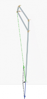
I did the simulation slightly different, the mechanism is seized, this allows the velocity to represent the SF at a single point instead of a range in translation as in the previous simulation. 2nd pivot is lifted, so we can see the velocity instead of reading a reaction force in numbers. The magnitude of the velocity is directly proportional to the SF at that position. Obviously exaggerated, there is no mass, so no inertia or friction for damping.
Green - Red - Blue
In your analysis, there is only one force vector. There is no interactions between forces. I suggest to do the following although I don't know if it is possible to do in your program.
1, Please see the diagram. Applying the force vector as in your 1st case (green) while add another force vector in your third case (blue), the force vector (black in my diagram) is the skating force.
2, Add mass.
I don't know if you plan to do these. In my opinion, it will reasonably reflect the reality. I expect that the skating force is linear and decreases cross the surface of record.
Attachments
Last edited:
1. There is only one force.
2. Not necessary, it should only reduce the magnitude of the velocity.
2. Not necessary, it should only reduce the magnitude of the velocity.
Further thought.
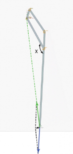
For a pivot arm, the angle X in my diagram is fixed. For a PT arm, it is not. What is the effect on the skating force (black arrow line) if we assume all the pivots are frictionless?
For a pivot arm, the angle X in my diagram is fixed. For a PT arm, it is not. What is the effect on the skating force (black arrow line) if we assume all the pivots are frictionless?
Attachments
Last edited:
“Magnitude and direction.” You’re absolutely right. Sigh. I failed that class.
The file is downloaded, but there’s no app to open it.
Sorry, Linkage runs only on Windows.
Just so we're on the same page, the Green-Red-Blue simulations are when those geometries are collinear with the groove force vector (less of a mouth full).
Your queries cause me to doubt.
Your queries cause me to doubt.
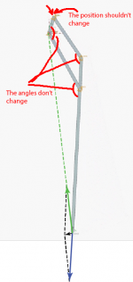
I looked at your video. The position of secondary pivot should be fixed (red line). And, the angles should change, but they don't in your video.
It is explained
Just so we're on the same page, the Green-Red-Blue simulations are when those geometries are collinear with the groove force vector (less of a mouth full).
Your queries cause me to doubt.
I understand it. In your 1st case, it is collinear with the green line, the primary pivot. In your 2nd case, it is collinear with the red line, secondary pivot. In the 3rd case, it is collinear with blue line, the arm wand. However, the model doesn't correctly represent my 6B arm. The reason I used a diagram to explain it. Your model is no different from a regular pivot arm except three different directions of force vectors.

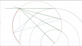
In an attempt to shed some light on the question of effective length of tangentially tracking tonearms, the image below shows a tonearm of physical length (short solid green) equal to the Thales circle radius. The dashed green represents the pivoting structures, which are unimportant for the argument. The reasoning will apply to any physical length of tonearm that is tangential at each concentric groove radius.
For a typical mid-groove stylus position, the point diametrically opposite the stylus on the Thales circle, is the instantaneous centre of rotation (IC). The IC is the position such that each point on the tonearm will move at right angles to the line joining the IC to the point, as the stylus follows the Thales path. The effective length (IC to stylus distance) is equal to the Thales circle diameter.
By a standard method applied to the two end points of the tonearm, the IC is the intersection of the two blue lines. As the stylus follows the Thales path, the IC follows the bold red arc on the Thales circle. This arc is the centrode.
The IC is important when determining the dynamic behaviour of tonearm mass/cartridge compliance lateral resonance. This depends on the moment of inertia (MI) about the IC. It should be obvious from the geometry that the MI varies considerably as the IC moves along the centrode. It is only when the stylus is over the LP spindle, that the MI resembles that of a conventional straight pivoting tonearm. On the grooved region of a disc, the MI will be variable and very different from a conventional pivoting tonearm.
Have any of the tangential tracking developers noticed that the tonearm mass/cartridge compliance lateral resonance frequency varies with position?
On a more troubling note, if the IC is the reference pivot for tonearm mass/cartridge compliance lateral resonance, then the resonance motion will be offset to the transverse groove modulation, inducing a scrubbing distortion. Is this a real concern or illusory? This could be perhaps mitigated by effective resonance damping.
Attachments
I made a gif animation to show the correct model of my 6B.
You ignored everything in my post.
Bon,
First, your Thales circle is way too small. The smaller the Thales circle, the larger tracking errors. For Birch style arms, the Thales circle at least is equal to the diameter of a record. This is why I looked at your diagram and got somewhat confused.
You raised a very interesting point. Personally, I don’t think it is a problem. I estimate that the lateral cartridge/arm resonance may vary cross the surface of record, but it should be very small. As long as the lateral cartridge/arm resonance is under 15 Hz, it shouldn’t be a problem. Let’s assume the lateral resonance varies from 8 Hz to 10 Hz cross the surface of record. It really doesn’t matter too much. In fact, it is measurable. I may try to measure it once I wire my 6B.
In order to reduce the inertia, I designed a silicone though for my 6B.
Last edited:
In an attempt to shed some light on the question of effective length of tangentially tracking tonearms, the image below shows a tonearm of physical length (short solid green) equal to the Thales circle radius. The dashed green represents the pivoting structures, which are unimportant for the argument. The reasoning will apply to any physical length of tonearm that is tangential at each concentric groove radius.
For a typical mid-groove stylus position, the point diametrically opposite the stylus on the Thales circle, is the instantaneous centre of rotation (IC). The IC is the position such that each point on the tonearm will move at right angles to the line joining the IC to the point, as the stylus follows the Thales path. The effective length (IC to stylus distance) is equal to the Thales circle diameter.
By a standard method applied to the two end points of the tonearm, the IC is the intersection of the two blue lines. As the stylus follows the Thales path, the IC follows the bold red arc on the Thales circle. This arc is the centrode.
It goes simpler than that. The movement of the tonearm is the superposition of two gyrations: once negative around the center of the Thales circle and once positive around the stylus.
You ignored everything in my post.
Let's forget collinear and force vector for a moment and examine the model itself first.
I made another gif animation from your video and put it side by side with my model.
Do you see the difference? The secondary pivot should be stationary. But in your model, it moves horizontally.
In addition to the movements of secondary pivot, all pivots are rigid joints except the primary pivot. This is why I said that your model is no different from a regular pivot arm.
Attachments
Additional comments about Bon's post.
There is also another possibility that lateral effective mass is heavier than vertical effective mass. The lateral effective mass for my 6B is 350 grams which the actual mass of the arm. It is obvious that the lateral effective mass will be heavier than vertical effective mass. However, it may not be a problem at all because the lateral resonant frequency can be equal or similar to vertical resonant frequency. I believe that the lateral resonant frequency will be the same as or close to vertical resonant frequency. It is very easy to measure both lateral resonant frequency and vertical resonant frequency. I may do that in the future, too.
There is also another possibility that lateral effective mass is heavier than vertical effective mass. The lateral effective mass for my 6B is 350 grams which the actual mass of the arm. It is obvious that the lateral effective mass will be heavier than vertical effective mass. However, it may not be a problem at all because the lateral resonant frequency can be equal or similar to vertical resonant frequency. I believe that the lateral resonant frequency will be the same as or close to vertical resonant frequency. It is very easy to measure both lateral resonant frequency and vertical resonant frequency. I may do that in the future, too.
Last edited:
Let's forget collinear and force vector for a moment and examine the model itself first.
I made another gif animation from your video and put it side by side with my model.
Do you see the difference? The secondary pivot should be stationary. But in your model, it moves horizontally.
In addition to the movements of secondary pivot, all pivots are rigid joints except the primary pivot. This is why I said that your model is no different from a regular pivot arm.
You ignored everything in my post.
2nd pivot
The secondary pivot should be stationary. But in your model, it moves horizontally.
I did the simulation slightly different, the mechanism is seized, this allows the velocity to represent the SF at a single point instead of a range in translation as in the previous simulation. 2nd pivot is lifted, so we can see the velocity instead of reading a reaction force in numbers. The magnitude of the velocity is directly proportional to the SF at that position. Obviously exaggerated, there is no mass, so no inertia or friction for damping.
Green - Red - Blue
You can deduce that the SF reduces towards the spindle fairly constantly, it is nearly linear, my previous calculation showed a slight increase in the rate of change, but it was not much. Very similar to Al's calculations but with a little bow downwards at the end, might just be a scaling issue on the axes.
I did note something in the Geometry, if the distance between the fixed pivots is increased by 0.7mm the sum of the adjacent sides is equal to the sum of the opposing sides, so I did that. It does not change the outcome.
Not sure if it is of any interest.
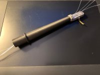
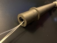
I started to wire the arm. In order to increase the stiffness of the arm wand, I inserted a 8 mm carbon fiber tube into the Markforged Onyx 3D printed arm wand and filled internal arm wand with Gorilla Glue. The arm wand is now really stiff. I know it is an overkill.
Attachments
- Home
- Source & Line
- Analogue Source
- Building a Tuthill/Reed 5A Tangential Tracking Pivot Tonearm