Hi sp33ls,
Instead of just changing those diodes, you could upgrade the whole power supply with an external 'u-beaut' unit instead - many choices - there's quite a noticeable change in the amp's sound
I use the older BIB circuit and looking to upgrade to the UltraBiB and lt4320 bridge but that's a bit extreme ...
The "Noir" HPA in the Store, uses that same exact circuit
_
Out of curiosity... What is the benefit of using this method rather than just adding some resistors in series as previously suggested?
Thank you for this.The "Noir" HPA in the Store, uses that same exact circuit
_
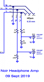
Can I ask some noob questions?
I can see that there is a 100Ohm resistor after the switching jack on left and right on the way to the power amp.
Where do the arrows indicate that is going?
Also, I am using microphone cable as rca. Is it right to split the shielding at the amp end for left and right?
If "arrows" means "triangles", those are schematic symbols which indicate "connected to ground". The triangle symbol is built-in to the schematic drawing piece of the LTSPICE software.
However these posts (#4040, 4041, 4046) don't have much to do with the main topic of this thread: WHAMMY
_
However these posts (#4040, 4041, 4046) don't have much to do with the main topic of this thread: WHAMMY
_
Attachments
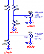
Or, if you were referring to the "arrows" pointing "upward" on the schematic, those simply show where the contact will be made with the circuit if the TRS male plug (your headphones) is not inserted. Inversely, it visually indicates by the little "nubs" on the end that when the male plug is inserted, that it will push the contacts in the switch up and away from the arrows, breaking the circuit to the RCA outputs.
See the datasheet for the Neutrik jack recommended in the "one-click" BoM / Cart for the Noir. You'll notice that there are 6 pins (TRS and their TN, RN, SN counterparts) vs. only 3 and that it is noted as a "switched" jack.
TRS would correspond to when the plug is inserted. TN, RN, SN would correspond to when the plug is not inserted.
As an addition to Mark's excellent explanation, I hope that covers all bases and that I've gotten it at least mostly correct. 🙂
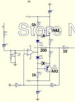
I finished assembling two units. In the first one, with the LME49720NA opamp, I have 0 mv of DC offset on the audio output. With an opa2604AQ the DC offset is around 10 mv. Using an LM833 this value rose to an absurd 100 mv. On the other board, I always have something like 25 mv on one channel, and 50 mv on the other, using different opamps. What could be wrong?
There is nothing wrong, the design specifies a FET device and because of the component values around the opamp a chip like a 5532 or LM833 will not give a low offset.
Look at the circuit. R5 and R8 need to be equal in value to generate minimal DC offset if you use a non FET opamp. The tiny (but not zero) current that flows out of the opamp input pins is the cause. If the DC resistance seen at each input is not equal you will generate an offset.
The FET devices do not suffer like this.
Does anyone have a good sharable LTSPICE file for the "WHAMMY" Pass DIY headphone amp? (Mark Johnson directed me here suggesting that a WHAMMY LTSPICE file might help.)
In particular I need a good simulation of stability.
I ask since I am debugging a different but somewhat similar headphone amplifier (different output stage). This different headphone amplifier behaves well with the stock NE5534 but somehow has the ability to kill OPA1611A and OPA228 op-amps dead in just a couple seconds with no audible output. Put the NE5534 back in and it works just fine. (It is a clone of the "Diamond Edition" Graham Slee Solo HPA.) I have never killed an OPA1611A or OPA228 before and I am currently stumped. So I thought that perhaps an LTSPICE simulation of stability might tell me something. Perhaps it is a stability issue or I am not sure what else it could be. Maybe a strange startup problem? I was thinking of adding an input series resistor but I don't want to sacrifice another OPA1611A or OPA228.
And if by chance anyone has a Solo HPA clone please let me know what op-amps you have successfully used.
Attachments
Last edited:
The board I am using is a somewhat similar (not identical) amplifier and uses single (NE5534/JRC5534) op-amps. (See the attached image.) I am hoping I can modify a good WHAMMY LTSPICE file to look at what is possibly going wrong with this similar but different HPA.
Attachments
I just need a good LTSPICE simulation file setup for stability analysis of an op-amp plus booster type HPA. In another thread Mark Johnson suggested that I ask here for a WHAMMY LTSPICE file. From there I will modify the simulation file.
The search thread function reports no matches for .asc and the four LTSPICE matching posts have no simulation files. So no one has ever simulated the WHAMMY headphone amplifier?
Does anyone have ANY LTSPICE simulation for ANY op-amp plus booster output stage HPA?
Does anyone have ANY LTSPICE simulation for ANY op-amp plus booster output stage HPA?
You might be forced to create one yourself from scratch. That's what you hoped someone else had done, but the answer seems to be Negative.
Yes. I would much prefer to use a nice simulation test bench setup by an LTSPICE expert. With any simulator there are details about how to really get the best results.
I simulated the WHAMMY with solder.
That output stage you have is not a follower, much different.
That output stage you have is not a follower, much different.

- Home
- Amplifiers
- Pass Labs
- "WHAMMY" Pass DIY headphone amp guide