The copper side is insulated by a kind of high voltage varnish. I used Plastik 70 from Kontakt Chemie. I’m sure Sheldon or one of the other knowledgable people here can tell you more.What exactly is an insulated stator.
This does probably not refer to the glass epoxy but to the copper traces on the outside.
When looking at those copper traces they are covered with a green film, just like PCB’s for electronic circuits.
Is this film inadequate in someway ?
Hans
The copper side is insulated by a kind of high voltage varnish. I used Plastik 70 from Kontakt Chemie. I’m sure Sheldon or one of the other knowledgable people here can tell you more.
That sounds as if it has been properly insulated, and nothing to worry doesn’t it ?
Hans
What exactly is an insulated stator.
This does probably not refer to the glass epoxy but to the copper traces on the outside.
When looking at those copper traces they are covered with a green film, just like PCB’s for electronic circuits.
Is this film inadequate in someway ?
Hans
None of this is meant to be critical of the Quad design overall. It's elegant and has stood the test of time, but it's also a bit fragile, and Quad made different design choices than most other manufacturers.
An insulated stator is one whose conductors are fully encapsulated by an adequate insulation to protect the panel and the user from the high voltages there. Practically speaking, there's no uninsulated path from the diaphragm/bias to the conductive stator. The insulation must be capable of withstanding thousands of volts, focusing the electrostatic field in the air gap, and handling transient overvoltage conditions without excessive energy storage. Overall, it makes for a more reliable, quieter panel that can be run at higher levels.
Martin Logan uses a thick nylon coating on their perforated metal.
In a Janszen or Acoustat panel, it's the PVC insulation on the wires that make up the stator.
In the Innersound later panels, it's a multi-layer circuit board with the conductors buried inside.
In some of the early Quads, the conductive layer is bare copper. The green film on circuit boards is solder mask. It's very thin, and not rated for high voltage.
The Quad design does increase the path length from the stator's conductive surface to the diaphragm, but it's not really an insulated design. The circuit board substrate is relatively thin, so the distance increase isn't as effective as something like the Beveridge design described in US patent 3,668,335, which uses a stator whose thickness is 3x that of the air gap.
Quad includes arc detection and voltage limiters to make their speakers more robust. The integrated dust covers also help. It's not a foolproof system though.
Mattstat is correct, the insulation on the modern quad panels is just solder mask, not really high voltage capable. But the insulation on acoustat panels probably isn't super high voltage either. That insulation is probably only rated for 600v or less. It's the air gap that really does the job.
I would say that the big problem with the quad panels are running naked is that it's quite difficult to vacuum out any dust bugs etc that get sucked into the panels. The front of the stators have open holes where it's possible, but not easy to vacuum out that side, and probably not overly effective. The back side has silkscreen screen glued to the inside of the stator which makes vacuuming that side out nearly impossible. The best way is to use compressed air and a vacuum together to try to blow the dirt parallel to the diaphragm and out the top or bottom using a blowing and sucking technique (I'll refrain from a "yo' mama" joke here).
The martin logan speakers seem a whole lot easier to vacuum out, and maybe that's why they can get away with it, and the stators are designed with no dust covers in mind so they are heavily insulated. I've never worked on an acoustat so I can't talk to their design. The audio static uses insulated wire as well and seems to do ok with no dust covers.
Another difference is that the quad diaphragms (modern quads) is about 3uM which seems to be a bit thinner than some of the non-dust cover speakers. That might be an issue was well.
Sheldon
Any pics of the electronics ? Hear lots about swapping capacitors in these but it would be good to know which and how accessible they are.
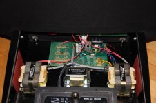

Any pics of the electronics ? Hear lots about swapping capacitors in these but it would be good to know which and how accessible they are.
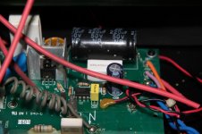
Not sure what you are hearing, but here's the lay of the land on the caps in a modern quad:
The majority of the capacitors in the speaker are high voltage ones. That gives you some very limited choices in swapping.
There's a bunch of 22pF caps in the delay line and a line termination capacitor of 1320pF (made up of 4 330pF ones). These are all high voltage caps. The very early quads used a different style of cap like a simple two plate glass cap. Some people say these sound better, I've never heard a significant difference but I've not spent much time sweating it. These are undoubtedly effecting the speakers sound, but I like the sound so I'm in no hurry to change them.
There are 14 20nF ceramic caps and a 47nf film cap in the power supply. The power supply is effectively completely isolated from the audio part of the speaker unless the neon bulb is in the middle of a blink, so changing these should make zero difference to the sound quality,
In the audio input and clamp circuit is where the caps that should be changed are. And this gets into some serious religious wars here. The important one to change regardless is the power supply filter capacitor. In every model of the modern quads, this is a 1000uF 16V unit. In the USA, the clamp circuit power supply is running right at or slightly above 16V. Change this while you are in there. I replace it with a 105C long life 1000uf 25v cap in every speaker I work on. Some of the later models (2912 etc) have already changed this to 25v. If that's the case you don't have to worry about it as much.
The audio signal enters the speaker through a 220uF bipolar electrolytic cap with a 1.5ohm resistor in parallel with it. replacing it entirely is tricky because a 220uf film cap is a coke-can sized unit, It will fit into any of the quads after the 63's. But it won't be a clean install by any means. What I do is add an 8.2uF polyprop film cap in parallel with the bipolar electrolytic. That can be zip-tied to the 220uf cap and will fit nicely in all speakers. Is it as good as replacing the electrolytic entirely, probably not, but it's mechanically so much better that I go that route.
The last cap in the signal path is a 1.5uf film cap in parallel with the primary winding of the input transformer. I replace this with a 1.5uf polyprop film cap on the 63's because that weird cap on the clamp boards sometimes fails in weird ways. For example it makes the speaker sound distorted at high volumes but not at lower volumes.
There are a couple small film caps for the antenna and clamp circuit but they are not associated with the audio signal in any way. And should not be changed unless the clamp circuit is not working
Before I go, since I'm on my soap-box already, I'd like to talk about wire in these speakers: There is no reason, absolutely zero, to change the internal wiring. There is a few inches of wire from the binding posts to the clamp circuit where the signal goes through 1.65ohm resistors, so gauge isn't an issue. Likewise the wire from the clamp circuit to the transformers is like a foot or less long and there is many feet of wire in the transformer. The wire from the delay line to the panels is also a couple feet long and the wire within each delay line is miles long. does the last two feet matter?
hope that helps,
Sheldon
quadesl.com

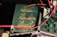
On the Crosby mod we rebuild the delay line caps using Teflon PCB material. Its a pain to rework that but the original ceramic caps are not the most linear. We used a product called corona dope to cover the exposed metal. It's also important to not have any sharp edges on any of the high voltage connections or you can have corona discharge.
It seems you can get COG ceramic caps at 5KV (minimum needed) from Knowles : https://www.knowlescapacitors.com/g...65c65a763/Knowles-MLC_catalogue_2017_10174_v2 however they may not be quick. Digikey has no through hole caps and a 1000 piece minimum for SMD.
We increased the HV supply impedance adding 100 Meg Ohm series resistors on each panel. This helps ensure constant charge operation and makes identifying bad panels easier. Longer start up time however.
The newer Quads have better mechanical construction and the newer metal inner grill is an improvement over the original. However they aren't much changed electronically or acoustically.
We increased the HV supply impedance adding 100 Meg Ohm series resistors on each panel. This helps ensure constant charge operation and makes identifying bad panels easier. Longer start up time however.
So do you get rid of the neon bulb and the 20meg resistor? Because when the neon bulb isn't struck (glowing) the impedance between the power supply and the panels is infinite already.
Sheldon
We left the bulb but increased the isolation between the panels. No way to validate the improved performance other than the feel good listening test. This was all 20+ years ago. And there is some minute leakage across the lamp when its off but its essentially open. We also experimented with regulated HV supplies. The benefit is stability. With the stock unregulated supply changes in the line voltage affect the output which has a small but real effect on the speaker's sensitivity. It would be a slow time constant so again hard to validate with instruments.
Would love to see how those Teflon caps look.On the Crosby mod we rebuild the delay line caps using Teflon PCB material. Its a pain to rework that but the original ceramic caps are not the most linear. We used a product called corona dope to cover the exposed metal. It's also important to not have any sharp edges on any of the high voltage connections or you can have corona discharge.
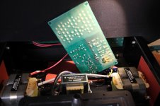
I made these for the 330 multi plate, for the 10 and 22 single plate.
Amazon Photos

They are definitely Teflon. I have the rest of the PCB material in my storage. Its .025" material I think. Its pretty thin.
I have not seen one of those kits in many years. The wire is a real PITA and not something I would do that way. BUT Richard Lees was convinced it made a big difference.
I have not seen one of those kits in many years. The wire is a real PITA and not something I would do that way. BUT Richard Lees was convinced it made a big difference.
Ah I see, so it is PCB material which means Teflon enforced with ceramic material or fiber glass as used for HF PCB boards by Rogers and others.
It is a Rogers material. It was expensive and hard to get then. Same with the dustcover film. Probably easier today. But still expensive.
They are definitely Teflon. I have the rest of the PCB material in my storage. Its .025" material I think. Its pretty thin.
I have not seen one of those kits in many years. The wire is a real PITA and not something I would do that way. BUT Richard Lees was convinced it made a big difference.
That wire and those links should be considered a hate crime...
I'm all ears as to why the last foot after miles of magnet wire makes a difference.
Last edited:
That wire and those links should be considered a hate crime...
I'm all ears as to why the last foot after miles of magnet wire makes a difference.
Sorry, I should have deleted this. I have a strong opinion of the usefulness, efficacy, and value of that sort of stuff. I should keep my opinions to myself.
Apologies to anyone whom I might have offended.
Sheldon
I'm inclined to agree with you on the wire. However at some point its in the "eye of the beholder" (ear of the beholder?) what sounds best.
There are some possible impacts of different wire but they have to do with the wire and associated parasitics and load/source stuff. In this case the source is pretty high impedance (step up transformer) so it could make a difference, I'm not sure what, but I won't discard it out of hand.
There are some possible impacts of different wire but they have to do with the wire and associated parasitics and load/source stuff. In this case the source is pretty high impedance (step up transformer) so it could make a difference, I'm not sure what, but I won't discard it out of hand.
- Home
- Loudspeakers
- Planars & Exotics
- QUAD 2805/2905 dismantling: in pictures (part 2)