I took Rayma's suggestion in Post #2 and added an L-Pad to the output of the preamp. Series Resistor was 47K and Parallel Resistor was 22.1K. Those were the closest values I had on hand that matched the resistors the L-Pad calculator suggested for an impedance of roughly 65,000 ohms and a 12 dB drop. Adding those L-Pads pushes the noise below the audible level even fairly close to the amplifier. I am still evaluating the sound quality but my first impression is it sounds fine. However, I think 12 dB is a bit too much attenuation since I think the gain of the preamp is only 10 dB. It isn't actually a problem but I thought I would try listening with less attenuation from the L-Pad. But I can't seem to find an L-Pad Calculator that lets me put in resistor values to calculate attenuation. They all seem to only take impedance and attenuation and output resistor values. Does any one have a calculator that lets you put in resistors and impedance and get back attenuation?
Also, I'm really in the dark about what impedance I should be using for the calculator. The preamp wants to see >50K ohms from the amplifier and the amplifier says it has an input impedance of 100K ohms and I found one post that suggested the preamp has an output impedance of 600 ohms. I used 65K ohms in the calculator because that gave me resistor values I have on hand but the truth is I have no real understanding of impedance in amplifier design.
Also, I'm really in the dark about what impedance I should be using for the calculator. The preamp wants to see >50K ohms from the amplifier and the amplifier says it has an input impedance of 100K ohms and I found one post that suggested the preamp has an output impedance of 600 ohms. I used 65K ohms in the calculator because that gave me resistor values I have on hand but the truth is I have no real understanding of impedance in amplifier design.
Attachments
Yours is Aikido Rev D i think. The schematic and values are for 280-300v
Do not remove R10, however; change C6 to 10uF. According to John from Aikido, he said "The higher the capacitance, the lower the noise null goes in frequency" so he told me to buy this and no problem at all.
https://www.mouser.com/ProductDetail/vishay/mkp1848c61050jk2/?qs=zDkSFN9STR99T7i7l5iS8w%3d%3d&countrycode=US¤cycode=USD
However, I just ordered this and will replace later.
Audyn Cap Q4 10uF 400V MKP Metalized Polypropylene Foil Crossover Capacitor
Does the value I listed the same as yours?
The PS does have voltage divider but I am not sure the value of R25. Mine is 47k. So when it connects at 300v, the pin 7 and 8 would be around 75-81v. At 100k, it probably shows 140-160v which it's too high. So 47k would be correct. Sorry, mine is 1 filament for 4 tubes while yours is 2 filament, 1 for each side so it may be different.
The values of C4 and C6 in the VTA SP14 design are 0.1uf. A hundred fold increase in those values seems like quite a lot but I don't understand their function in the circuit.
R25 is 100K in the SP14.
Also the high voltages measure 272 VDC on the board which is within the design's specification.
Ok, 100k would be correct for it. I think you would get between 70-77v
John from Aikido said Terminating Resistor would help by bridging input hot and ground with 100k-1M. What the total value for series 47k and parallel 22.1k?
John from Aikido said Terminating Resistor would help by bridging input hot and ground with 100k-1M. What the total value for series 47k and parallel 22.1k?
John from Aikido said Terminating Resistor would help by bridging input hot and ground with 100k-1M. What the total value for series 47k and parallel 22.1k?
Sorry but I don't understand what you are saying/asking. What is a terminating resistor and what do you mean by bridging input hot and ground? What does 100K-1M refer to? And what do you mean by total value?
In your post #41, what is "Series Resistor was 47K and Parallel Resistor was 22.1K" for? and formula to get that value? Oh L-Pad is voltage divider?
I didn't apply the ground issues in the manual so I am not sure if it works.
Do you have the full manual for the Aikido All-in-One octal design? Googling I find the 9-pin version online but not the 8 pin 6SN7 version. I hadn't realized the SP14 and that version were virtually identical except for some changes in the power supply.
Yes, the 47K and 22.1K were the values of the L-Pad voltage divider that I added to the outputs of the SP14. That did solve the hum problem by reducing the output by about 12 dB and forcing that noise below audible levels. I'm not sure how, if at all, it changes the character of the sound. So far it seems to be working quite well but I haven't done any critical listening tests.In your post #41, what is "Series Resistor was 47K and Parallel Resistor was 22.1K" for? and formula to get that value? Oh L-Pad is voltage divider?
Clearly, it would be better to have the SP14 not be noisy but nothing I have tried has reduced or even changed the noise/hum coming off the SP14 except for rotating the pot which simply shifts the noise from the left and right channels, something I am still puzzled by.
Just remove R10 from both channels (at the same time) and see if the noise increases or decreases.
Last edited:
Can you check the voltage of pin 7 and 8 to see if you get around 70-80v. If you get more than that, it's best to change R25, then you can remove L-Pad voltage divider.
Did you actually mean remove R10 as in break the connection between C6 and R8/ R9? I'm reluctant to do that without having a reason since I don't understand circuits well enough to know what the ramification of that is.Just remove R10 from both channels (at the same time) and see if the noise increases or decreases.
I did jumper R10 and it made no difference to the noise.
I think my board and your board may have different conventions for numbering pins. On my board the sockets are numbered counterclockwise starting with 1 being to the right of the notch and 8 being to the left of the notch. On the diagram of the board pins 7 and 8 are labelled F, I presume for filament. Pins 1 and 2 are labeled G1 and P1. Pin 3 is C1, Pins 4-6 are G2, P2, and C2.Can you check the voltage of pin 7 and 8 to see if you get around 70-80v. If you get more than that, it's best to change R25, then you can remove L-Pad voltage divider.
I measured with tubes still in place. I have no idea if that is right or not. On the back channel the 7-8 pins measure 6.0 vdc on both tubes. On the front channel Pins 7-8 measure as 6.08 vdc.
On the back channel Pins 1-2 measure 129 VDC and Pins 4-5 measure 123.6 vdc. On the front channel Pins 1-2 measure 130.8 vdc and Pins 4-5 measure 123 vdc.
I didn't measure Pins C1 or C2 against anything.
Voltages at the points on the board where you have access show the high AC in measures 268 volts. The 6 vac in measures 6.7 volts. The H- H+ points measure at 6.04 volts for the back channel and 6.12 volts for the front channel.
I think my board and your board may have different conventions for numbering pins.
Pin numbering is usually as per the tube manufacturer's conventions, not the board manufacturer's.
The labelling on the board refers to F=filament, P=plate, G=grid, C=cathode. The subscripts 1 and 2 refer to the two separate triodes contained in each tube.
It would REALLY help you if you spend a bit of time understanding the circuit - even if only to the point where you know what voltages to expect at a given test point.
It would also help if you posted an "as built" schematic diagram. That is then the reference document for anyone trying to assist.
Exactly how do you expect me to "spend a bit of time understanding the circuit"? Perhaps I could spend the next six months at a community college taking courses in basic electronics and circuit design? Or maybe I should go all the way and just get a degree in electrical engineering? You might as well tell me to go get a basic understanding of Greek to help improve my English. This is a hobby, not a profession, and despite a surprising amount of effort on my part, my casual interest is not going to result in my understanding the circuit or being able to predict what voltages to expect at a given test point.It would REALLY help you if you spend a bit of time understanding the circuit - even if only to the point where you know what voltages to expect at a given test point.
It would also help if you posted an "as built" schematic diagram. That is then the reference document for anyone trying to assist.
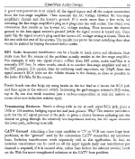
I bought the PCB from Tubes 4 HiFi and they don't provide much information. The board is built exactly per their schematic which I posted earlier. The specific parts values don't exist in an annotated schematic but you can see them in this attachment.
And while I appreciate everybody's efforts in trying to debug the hum, I started this thread with the question of whether I could simply attenuate the volume at the preamp's output since the hum is constant regardless of the signal strength into the preamp although it does move from the left to the right channel based on the setting of the pot. So far Rayma is the only person that has actually addressed that question and adding an L-pad after the output does make the hum inaudible although I haven't decided yet whether it has any negative consequences.
Attachments
woah, pull back tiger. I didn't suggest you get design skills, I suggested you learn how the fundamentals of the circuit operate.
I did it. I'm an HR manager. Not an electronics technician. I'm no expert, but I can understand what the circuit is doing, most of the time, and if not I can understand it once its basic operating premise is explained to me.
If that's way too much trouble for you, you may want to reconsider playing with a hobby that generates lethal voltages. Lego or something might suit better.
Of course the L pad will reduce noise. So will totally taking away the pre-amp, and that effectively what your L-pad has done. There is no nett amplification, so now you have a fancy switch.
I don't need amplification. This is driving a 400 Watt Class D amp not a First Watt F4. Even without a preamp I need 30 dB of attenuation to save my hearing. And I have other preamps if what I want is a switch which it isn't. I want to see what having 6SN7 tubes in between my DAC and my Amp does or doesn't do. So far my experience has been preamps don't make things better. Certainly neither my Schiit Freya, nor my Waynes BA2018 Linestage, nor my Elkit TU-8500DX have made the sound quality any better. But I have a couple of dozen 6SN7 tubes and quite a bit of curiosity and time on my hands so I decided to give the SP14 a try. Personally, I think the noise is probably a defect in the circuit that comes from less than perfectly matched components but as I said I don't understand the circuit well enough to assert that as a fact. But this is the 8th amp/preamp I have built and I don't appreciate you telling me what I REALLY need to do.Of course the L pad will reduce noise. So will totally taking away the pre-amp, and that effectively what your L-pad has done. There is no nett amplification, so now you have a fancy switch.
- I don't need amplification.
- Even without a preamp I need 30 dB of attenuation to save my hearing.
- So far my experience has been preamps don't make things better.
- ....But this is the 8th amp/preamp I have built .....
Your own words say you really don't need a preamp but either nothing or a buffer as in 99% of similar cases. Simple.
If one does not need amplification why add amplification and then attenuation? 😀 It should be no surprise that results don't become better by adding the wrong items in a chain for the 8th time. Maybe you could use a different superfluous circuit for the job?!? The 9th 🙂 Make that a buffer to prevent the 10th. Study beforehand what it is you need (0 GAIN, high input Z, low output Z) and don't stare at the tube type but find the best tube + circuit for the job. This to avoid the "just doing something" virus as it is very wide spread and once caught nearly incurable as well.
Last edited:
"But this is the 8th amp/preamp I have built and I don't appreciate you telling me what I REALLY need to do."
And yet, here you are, asking for help because you don't know what you are doing.
If you don't need amplification or switching, a cathode follower built with your 6SN7 tubes is about as simple, clean and transparent a circuit that you can have to try out tubes. The circuit would have a gain of approximately 0.9, so no chance of damaging your hearing or your amp. This is the circuit I first built and learned on. It has an absolute minimum of parts so it was easy to build point to point (no pcb), troubleshoot and get going.
It operates as a buffer. The input signal is not amplified in voltage, but the current capablity is increased. In other words, the input signal is replicated at the output stronger, but not bigger.
The technicality of why this happens are immaterial to you at the moment, so no point dwelling on it. But this circuit delivers what you have said you want.
Can you check the voltage of pin 7 and 8 to see if you get around 70-80v. If you get more than that, it's best to change R25, then you can remove L-Pad voltage divider.
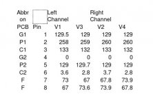
Per your request here and by PM I measured all the pins referenced to ground for all 4 6SN7 tubes. I think the PCB has flipped the pin assignments for G1, P1, and C1 with G2, P2, and C2 from what is shown in the schematic or the board is mislabeled. Since I though they were symmetrical in the tube I doubt that matters.
Volts DC Measured Against Ground
Abbr on Left Channel Right Channel
PCB Pin V1 V3 V2 V4
G1 1 129.5 129 129 129
P1 2 258 259 260 260
C1 3 133 132 133 132
G2 4 0 0 0 0
P2 5 129 129.7 129 129
C2 6 3.6 2.8 3.7 2.8
F 7 73 67 67.8 73.9
F 8 67 73.6 73.9 67.8
I can't figure out how to make that table format correctly so I am also attaching a JPEG of that table.
Attachments
Exactly how do you expect me to "spend a bit of time understanding the circuit"? Perhaps I could spend the next six months at a community college taking courses in basic electronics and circuit design?
Maybe read some books? I've figured out how this stuff mostly works without going to school or diving in to engineering deep levels. Part of the fun of a hobby and building stuff is learning from it. I do find it comical you are here blaming a circuit being defective ,while at the same time admitting you don't understand what is going on with it.
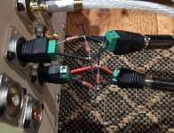
BTW I was cringing looking at the way the RCA jacks were wired up and that u-shaped common ground for both the input and outputs. That's what I would be looking at. Here is a good video explaining tube amp grounding. Mark's channel is full of great info.
Understanding Vacuum Tube Amplifier Schematics - Grounding - Part 6 - YouTube

- Home
- Amplifiers
- Tubes / Valves
- Attenuation After Noisy Preamp?