moved on to this for now while i wait for the parts for 3140
report that came ti this is.
powers on ok one channel ok
other channel sound in and out
so ill have a look at this one 😉
update
problem is i cannot find TP1 or TP2 which i presume means test points and they are supposed to be on the underside of the board, bit i cant find them for love nor money
maybe someone on here has had the same issue and knows where they are?
Last edited:
managed to set the centre ok but the idle current adjustment doent work on either channel so ive got to try and find out why
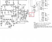
D615, so the one across the relay.
Adding a resistor will alter the voltage across the relay coil but I can't say by how much without knowing the ohms of the coil alone. Its easy to work out, the 1k and the relay are effectively a single resistor in series with the 680 ohm. So if you know the supply voltage and assuming pin 6 goes down to zero volts you can easily work the voltage out 🙂
The resistor can only lower the voltage and there are much better ways of doing that also save power, not increase it like a resistor.
but why do it in the first place?
the lamp is on with this one but dim so i cant see much being wrong with this one.
i cant seem to adust the idle as per the tech spec, but ill work on that tomorrow.
i replaced the 2 no 100ohm trimmers with new ones as the others were a bit crappy.
the lamp is on with this one but dim so i cant see much being wrong with this one.
i cant seem to adust the idle as per the tech spec, but ill work on that tomorrow.
i replaced the 2 no 100ohm trimmers with new ones as the others were a bit crappy.
Last edited:
No idea. Can you be certain it is not a factory afterthought mod... it happens.
Relay coils will often work well on lower than the stated voltage and doing that reduces how hot they get.
Ideally the relay should snap in smartly with full voltage and then the voltage reduce to a holding value... which is easy to do with a cap. The cap is charged to the full supply voltage and then when the chip turns the relay on there is full voltage available for an fraction of a second. After that a series resistor limits current and the voltage falls. A 24 volt relay coil will 'hold' down to about 6 volts but it will not pull in with a low voltage.
A series Zener is often useful for dropping excess voltage rather than a resistor.
I own one, for over 30 years now. Still in use as a power amp for my subs. Nice amp, recently recapped it and that made a world of difference. It broke down a few times, every time because plain high value resistors failed or had significant changed resistance. Probably they did not use the best batch back then. Not the kind of component that usually fails so be aware.... I had 22k resistors that measured 15k and 18k that measured over 30. Carefully check all voltages in the entire amp and investigate any deviations.
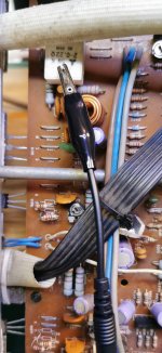
Vaguely recall there was a service bulletin or similiar where they had reports of relay drop outs. The fix called for adding a resistor on the solder side of the board possibly in parallel with R676? Resistor in parallel with the (flyback) diode seems odd.someone has put a 1k resistor in parellel with D615, why would they have done that doyou think? it wasnt fitted as standard and you can tell it was done after as it was badly fitted
edit: not a huge fan of the 3150, reworked 2 units, they only sounded ok. Tones,pace were ok but soundstage was miserable...
Last edited:
No idea. Can you be certain it is not a factory afterthought mod... it happens.
Relay coils will often work well on lower than the stated voltage and doing that reduces how hot they get.
Ideally the relay should snap in smartly with full voltage and then the voltage reduce to a holding value... which is easy to do with a cap. The cap is charged to the full supply voltage and then when the chip turns the relay on there is full voltage available for an fraction of a second. After that a series resistor limits current and the voltage falls. A 24 volt relay coil will 'hold' down to about 6 volts but it will not pull in with a low voltage.
A series Zener is often useful for dropping excess voltage rather than a resistor.
main issue at the moment is i cant alter the idle current.
when i do it as per the instructions there is no movement on the meter at all, as i turn the pots the lamp just gets brighter or dimmer, i guess as the current is increased, but no change in the meter readings.
worked ok doing the centre no problem so nothing wrong with the test points ,or the pots as they are new ones.
going to start having a look at this a bit later after ive been out for a nice long walk 🙂
actualy other than the series 20-3020 ive not found any other NAD ive worked on that comes up to the standard of the 3240PE or the 3130 which are both great sounding ampsVaguely recall there was a service bulletin or similiar where they had reports of relay drop outs. The fix called for adding a resistor on the solder side of the board possibly in parallel with R676? Resistor in parallel with the (flyback) diode seems odd.
edit: not a huge fan of the 3150, reworked 2 units, they only sounded ok. Tones,pace were ok but soundstage was miserable...
It sounds like the adjustment is working if the bulb increases in brightness.
Just measure voltage across the emitter resistors in the normal way to start with. It has to be working.
Just measure voltage across the emitter resistors in the normal way to start with. It has to be working.
i understand what you are saying, but in my mind is still the question, why is it sitting at zero when i try and adjust
it should be between 4.4 and 11mv but it doesnt move off zero at all on both channels so there must be a common problem right? just where i have to find it.
the emitter resistors you refer to are R659/660?
it should be between 4.4 and 11mv but it doesnt move off zero at all on both channels so there must be a common problem right? just where i have to find it.
the emitter resistors you refer to are R659/660?
It sounds like the adjustment is working if the bulb increases in brightness.
Just measure voltage across the emitter resistors in the normal way to start with. It has to be working.
ok so i think i might be getting somewhere here
i think the left channel is ok,it says to let it warm up for 5 mins and i proberbly didnt first time around ,but the left channel adjusts up ok so set at 8mv and centre is 0v
right channel is at -11mv(closest i can get) so i think the issue is with the right channel and thats where im going to concentrate my efforts starting with the voltages from the beguining
For the centre voltage it is the voltage across the speaker terminals that is the one that matters.
If you have zero volts done that way and then you measure from chassis ground and see -66mv at the output then that is probably because of slightly different ground potentials within the amp which is not normally a problem.
(If all grounds were absolutely all the same and had zero resistance between them then we would not have all the problems we see with ground loops and hum and buzzing. So we have to work around them and create 'local' grounds relevant to the circuitry in that area. It is common in digital stuff like CD players to see analogue ground, digital ground and perhaps a separate ground for the motors. They all seem to connect together but the way they do is critical to get low noise because of small voltages and circulating currents)
its just the idle
something is just niggling at me because i cant adjust it and if you try to adjust it the lamplights up realy bright, and its always on, dim but always on
ive checked all the voltages, right from the power supply, replaced that resistor that was open circuit, and the rest of the voltages seem ok, and yet i just dont think its right
i certainly wouldnt want top plug it into speakers as it is.
Lets start at the beginning... it gets a bit confusing what is going on you see 🙂
1/ The centre voltage adjusts OK to zero volts as measured at the speaker terminals. Yes?
2/ The idle current doesn't register as altering on the meter and yet the bulb goes brighter or dimmer as you turn the preset. Yes?
If those two are a 'yes' then connect your meter across either of the 0.22 ohm and with the preset turned to make the bulb at its dimmest measure and record the voltage across the resistor.
What is it?
Now turn the preset so the bulb is brighter and measure the voltage again.
What is it?
Also silly question... I'm assuming the speaker relay is closing correctly and you really are measuring the true DC offset and not just some floaty value because the relay is open.
1/ The centre voltage adjusts OK to zero volts as measured at the speaker terminals.
2/ The idle current doesn't register as altering on the meter and yet the bulb goes brighter or dimmer as you turn the preset.
yes to both above
i do this in the morning and get back to you
thanks🙂
2/ The idle current doesn't register as altering on the meter and yet the bulb goes brighter or dimmer as you turn the preset.
yes to both above
i do this in the morning and get back to you
thanks🙂
- Home
- Amplifiers
- Solid State
- NAD 3150