@Craigl59 - My apologies. I did not mean to be inappropriate or unproductive. That sentence on its own, when read on its own, may read that way. It was not my intent.
My intent was to describe a way to determine if there is in-fact a board manufacturing issue (or other issue) using what I perceive to a very simple method. Signal lost describes it much better than I, so I will not repeat it, but will paraphrase it again.
If you are looking for a board issue, screw the schematic. Trace the board.
I personally see a very low likelihood of 2 pairs of both A and B boards being manufactured incorrectly among a subset of 100s, but I was willing to walk you through how to prove or disprove your hypothesis.
I hope that shows proper emphasis without being offensive in any way.
Truly wish you the best in figuring all this out. I'll continue to work on brevity and conveying my intent and instructions more clearly. It's best if others coach you through the rest due to my inability to convey my intent.
Last edited:
@Craigl59
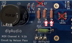
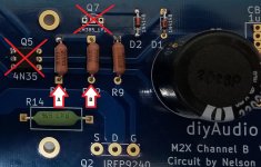
Please take a measurement of the resistance between the two points A and B. Q5 (4N35) and Q7 (LM385_1P2) should not be installed.
Also swap the two measuring sensors between A / B and measure again.
Tell us the values of the two boards.
Please take a measurement of the resistance between the two points A and B. Q5 (4N35) and Q7 (LM385_1P2) should not be installed.
Also swap the two measuring sensors between A / B and measure again.
Tell us the values of the two boards.
Attachments
But he's done that... over and over... see "above". 
@Craigl59. I am, of course kidding, and making fun of myself. stonegreen has conveyed with far fewer words and two pictures, what I've been trying to describe for the last two days. There may be more measurements to follow, but that's the start.
@Craigl59. I am, of course kidding, and making fun of myself. stonegreen has conveyed with far fewer words and two pictures, what I've been trying to describe for the last two days. There may be more measurements to follow, but that's the start.
The folks on this site are the best -- willing to help another and spend their time and effort to educate. Have the replacement boards coming and will build the post-Edcor portion of the cards in 3 stages -- each accompanied by rigorous checks against the schematic and the one currently working board. After each will be checking the values that have caused troubles and are detailed above, especially R14 to Pin 2, 4N35.
If there is any helpful information found, will supply it then.
Until that time, it is not necessary to provide me with any additional help. It is unnecessary and too much trouble on your parts.
If there is any helpful information found, will supply it then.
Until that time, it is not necessary to provide me with any additional help. It is unnecessary and too much trouble on your parts.
stonegreen: the checks you describe have been done at least 3 times above (see post 5570) and the values have always been R221 -- both on working and non-working boards. Again, no need to provide additional help.
Last edited:
I think it's very likely that member grataku assembled both Cedarburg boards correctly, with correct value components and brand new, non-counterfeit, correctly functioning AD797 chips purchased from a fist-tier electronics distributor. In which case, the boards are working exactly as designed, but the listening experience they provide is (strongly) not-preferred.
Way back in this thread, thousands of posts ago, another member posted that Norwood was powerfully suckful; unbearable and un-listenable. Just like all the other audio circuits he had ever built and listened to, using the 110 MHz Harris/Intersil/Renesas HA5002 video cable driver chip. He had convinced himself that the presence of an HA5002 in an audio signal chain, guarantees bad sound. Yet quite a few other M2x builders truly love Norwood and the sound it makes (including @pfarrell).
What does it mean? I think it means: Good thing there are so many M2x input stage daughter cards to choose from. If you don't like A, you have the option to try B (and C, and D, ...). Find one that you like. Possibly even find the one that you like best. Then don't get too concerned if other people like something else.
Baskin Robbins sells 31 flavors and I'm allowed to prefer Jamoca Almond Fudge while you favor Mint Chocolate Chip. It's all good.
My Cedarburgs are awesome. But, as I think Mark is alluding to, as with anything in audio your favorite flavor may not match my favorite flavor. I am forever grateful for the opportunity to try all the different 'flavors' and see which one appeals to me.
Regards,
Dan 🙂


LOL. I expected the Cedarburg to be the best and I was strongly surprised and disappointed. If you use the M2x as a subwoofer amp I would definitely recommend it but not for any other part of the freq spectrum.
I am sitting here wondering how can a simple buffer have such profound effect.
Time to build the original buffer and see if the sound gets close to the magic Vfet amp.
I am sitting here wondering how can a simple buffer have such profound effect.
Time to build the original buffer and see if the sound gets close to the magic Vfet amp.
Need some help from the more knowledgeable people here:
- I am powering up my M2x w/Mountain View input boards for the first time (Antek 4218 toroidal producing +/-25.8Vdc from PSU with 176,000uF total capacitance)
- I powered up each board independent with a 100W DBT. DBT lights and dims almost immediately (~0.5 sec), then I see the Vdc ramp up on the DMMs (one on positive rail one on negative rail) and they ramp up to operating voltage after 5-6secs.
- Then after 25-30 seconds, the voltages on the PSU (both DMMs) starts dropping and the DBT begins light up - this slow decrease in voltage continues for about 45 seconds has passed and the voltages stabilize at +/-15.85Vdc (both rails are within 0.12V of each other the entire time it is powered up).
- Nothing appears to be heating up, finger test on Output Mosfets and 0.47 bias resistors, everything is room temperature after 2-3 minutes.
Question - only my second Class A amp and so I am thinking this is "normal" as the bias starts to come up and draw current, but wanted to confirm because the 9V drop and DBT lighting up has me worried.
The bulb may not be high enough wattage for the amp's idle current. It will always light up
if it is too small for the amplifier, which NP says draws about 200W when warmed up.
Since the amp seems ok, go ahead and remove the DBT, and fire up the amp,
and follow the written procedure.
if it is too small for the amplifier, which NP says draws about 200W when warmed up.
Since the amp seems ok, go ahead and remove the DBT, and fire up the amp,
and follow the written procedure.
Last edited:
It seems other builders have experienced something similar (post #1225+)
https://www.diyaudio.com/forums/pass-labs/321925-diyaudio-watt-m2x-123.html#post5652024
https://www.diyaudio.com/forums/pass-labs/321925-diyaudio-watt-m2x-123.html#post5652024
to bullittstang #5631
Hello bullittstang,
the phenomena with the M2X on the dimbulbtester is well known. Dimbulbtester goes off and lights up again after a few sconds.
This was mentioned and discussed a few times in this very long thread.
My M2X does exactly the same. I would test it without any speaker (and without the dimbulbtester!) and adjust the offset.
If you can't adjust your offset at speakeroutput below 50mV (better below 10mV) you should read the info about the 'blasphemous heresy' -change = change of resistor R6 and trimpot.RV1:
post#3 (in this thread) from Mark Johnson:
3. WARNING: BLASPHEMOUS HERESY! DO NOT READ THIS! Some DIY builders of the M2 amplifier, using the very fine “Tea‐Bag” circuit board, have reported a problem to the diyAudio forums. Their M2 amplifier’s output offset voltage is negative, and no setting of trimmer resistor RV1 removes this negative offset. I would like to gently mention a possible fix: leave R7=47K, but change R6 to 37K and change RV1 to 20K. Now (R6+RV1) can vary from 37K to 57K, in other words, from (10K less than R7) to (10K more than R7). This lets you null out either polarity of offset voltage. However, to faithfully reproduce Nelson Pass’s original M2 design, the M2X schematic and PCB silkscreen do not include this modification. M2X has R6=47K and RV1=5K. If you decide to make this R6,RV1 modification on your M2X, don’t tell anyone. And don’t quote me.
Cheers
Dirk 😀
Thanks guys - thought I read the “strange behavior” in this thread but with the recent issues Craig had, I was gun-shy to chalk it up as normal.
I did the “blasphemous update” from the beginning - my OCD couldn’t take an amp this nice being anywhere but at zero offset.
Thanks for the links and reminder as well as confirmation - didn’t want my very slow progressing (6 months) project to go “poof”
I will post some pics when it’s complete, still waiting on some RCA jacks and wire for the inputs.
This has been answered, but I always found this picture super helpful...
https://www.diyaudio.com/forums/pass-labs/281520-official-m2-schematic-336.html#post5902652
Post #3355 in the Official M2 Schematic thread if the link doesn't work for everyone.
Edited to add clarity/accuracy re: the thread name.
https://www.diyaudio.com/forums/pass-labs/281520-official-m2-schematic-336.html#post5902652
Post #3355 in the Official M2 Schematic thread if the link doesn't work for everyone.
Edited to add clarity/accuracy re: the thread name.
ISIMH - couldn’t get the link to work, so thanks for the actual post#. Totally agree - that graphic should be in the build write-up, it explains exactly why I was freaking out.
@Craigl59
Please take a measurement of the resistance between the two points A and B. Q5 (4N35) and Q7 (LM385_1P2) should not be installed.
Also swap the two measuring sensors between A / B and measure again.
Tell us the values of the two boards.
Need some help from the more knowledgeable people here:
- I am powering up my M2x w/Mountain View input boards for the first time (Antek 4218 toroidal producing +/-25.8Vdc from PSU with 176,000uF total capacitance)
- I powered up each board independent with a 100W DBT. DBT lights and dims almost immediately (~0.5 sec), then I see the Vdc ramp up on the DMMs (one on positive rail one on negative rail) and they ramp up to operating voltage after 5-6secs.
- Then after 25-30 seconds, the voltages on the PSU (both DMMs) starts dropping and the DBT begins light up - this slow decrease in voltage continues for about 45 seconds has passed and the voltages stabilize at +/-15.85Vdc (both rails are within 0.12V of each other the entire time it is powered up).
- Nothing appears to be heating up, finger test on Output Mosfets and 0.47 bias resistors, everything is room temperature after 2-3 minutes.
Question - only my second Class A amp and so I am thinking this is "normal" as the bias starts to come up and draw current, but wanted to confirm because the 9V drop and DBT lighting up has me worried.
What's the reason for such low PS voltage ~16 V?? I first used an antek 18+18 200VA and the voltage went down to +/-20.5V under full bias which is about 2.6A. I have the usual CRC filter in the PS.
Yon mentioned 176mF caps, what about the low pass filter? I didn't like the low voltage supply and I decided to use a 200VA 21-0-21 and the voltage is a much better +-25VDC under full bias and the amp sounds much better.
- Home
- Amplifiers
- Pass Labs
- The diyAudio First Watt M2x