Alekk it may be an optical illusion again. But worth checking. Is the "black post" speaker terminal on the right hand side of your picture in front of the black isolation spacer or behind it? In both of the pictures it looks to me like it is behind.
You referred to a DSP - if it is a mini-dsp I use one to feed my ACA(s) - and there isn't any issue at all. They work very well together.
You referred to a DSP - if it is a mini-dsp I use one to feed my ACA(s) - and there isn't any issue at all. They work very well together.
add sub to aca + pensil setup?
Hi all -- I recently built an ACA and a set of Alpair 11MS 6.5" metal cone pensils. I love the set up but am thinking it could use some more bass. I'm considering building a sub to add to my setup. Any thoughts/advice on what kind of sub -- what driver, what type of enclosure? Crossover? I'm a stereo building noob but loving what I've done so far and this community. Thanks for your thoughts/advice.
Hi all -- I recently built an ACA and a set of Alpair 11MS 6.5" metal cone pensils. I love the set up but am thinking it could use some more bass. I'm considering building a sub to add to my setup. Any thoughts/advice on what kind of sub -- what driver, what type of enclosure? Crossover? I'm a stereo building noob but loving what I've done so far and this community. Thanks for your thoughts/advice.
My Carfrae horns are massive full range speakers augmented with a pair of subwoofers and plate amplifiers. Recommended 4-20Watt max for the amp which is one of the reasons I’m using ACA to drive them. The original speakers had a ported 10 inch subwoofer under each one. I chose Seas 10inch sub and passive radiator combination as a safer option as there’s no calculation or guessing needed around port length or diameter. I used a hypex DS2 plate amp which is 100w class D to drive them. I split the speaker cable at the plate amp so it takes a small signal and then a shorter length to th main driver. ACA never sees a load. You can set the gain and crossover point on the plate amp till it sounds right. If the overlap between the sub and speaker is too much bass will be boomy. It’s a great setup with lots of adjustment. When I upgraded speaker cables and got more bass I was able to turn a knob and job done. Hypex DS 2 are out of production but hypex have the same controls on newer products. Seas passive radiator I used is discontinued too. There’s a theory that the passive radiator should be bigger than the sub but my matching combination work fine. The only thing I haven’t played with is adding weight to the back of the passive radiator which would drop the bass even further.
Last edited:
What about this as a less expensive plate amp for the kind of project you suggest?
https://www.parts-express.com/pedocs/manuals/300-784--dayton-audio-sa70-manual.pdf
https://www.parts-express.com/pedocs/manuals/300-784--dayton-audio-sa70-manual.pdf
Yep that's got the crossover and inputs and outputs you need. I wasn't sure about the quality of the internal bypass so added some jumpers on the outside.

Re-measured in slightly better conditions (save for the LF rumble), -9dB left channel compared to the right at 1kHz
Not denying that the hum may be from the source. The symptom specifically is that the hum is traveling through the right channel board/ input wiring (with the left channel input exhibiting the same behavior) to the left channel board, but the hum is not present in the right channel board ever. I can take a short video to clarify.
Both measured as expected, 50k at the input, 1k at the output.
Test point measurements attached, both boards measure nearly identically.
Bizarre.
I assume you have ruled out faulty sources and or faulty speakers? And swapping either round or using another known good source still gives a lower out from the Left (white?) channel.
The two boards do look the same and all the components do look in the correct locations.
I wonder if understanding how you get a hum from the left channel with an input to either Red or White RCAs might be a clue (or red herring?).
Do you get the same result if you remove the +ve lead from the board or boards?
There are multiple -ve returns but it might be useful to make sure they are all actually at 0 volts.
More thought needed.
There has to be some leakage across a component that should be "airtight" is all that I can think of at this point, by the way the issue presents itself.
When the RCA ground is left disconnected (only center pin inserted), the hum present is much quieter and at half frequency of what is present when ground is connected, and is only present on that respective channel (if left RCA is inserted, 1/2f hum is present only on the left, and the same can be said of the right channel), but once ground is present on either channel, only the left channel has the dreaded hum. I've gone through everything I can think of at this point, considering ordering some new components to rule out something faulty if a re-wire doesn't fix the issue.
Thinking about this last night. Wonder if your system ground at the power connection is in trouble. Maybe the supply connector itself or the solder connection to it. You could test my theory by desoldering the center pin and sticking it into the supply cord, and holding the outer conductor up against the ground bus. Or use an alligator clip for ground.
scrape it more, use flux or calophone for further cleaning
but, proper size soldering tip is of equal importance
crank it to max, it is much better to solder with higher temp and fast than to gnaw it for half day
but, proper size soldering tip is of equal importance
crank it to max, it is much better to solder with higher temp and fast than to gnaw it for half day
scrape it more, use flux or calophone for further cleaning
but, proper size soldering tip is of equal importance
crank it to max, it is much better to solder with higher temp and fast than to gnaw it for half day
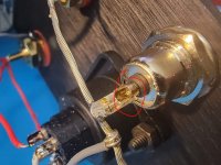
Thank you. I got it to work with more scraping with an alcohol pad with the little screwdriver to also remove any oils. I didn't have any Flux and I guess now I understand why it's nice to have around. The heatshrink should help to reinforce this connection as well as keeping it from touching the other lead.
I just have to wire up the LEDs and I'm ready for my smoke test. This work day is going to be longer than normal. Haha
I can't get any solder to stick in here (center of the barrel). Any tips? I cleaned it off with alcohol but no luck. I tried scraping it with a tiny screw driver, no luck.
Looking at the other solder joints it looks like solder temp is generally too low.
Maybe good to re-flow so all joints looks shinny and with "smooth" surface.
Do you use solder with low melting point? 180 C or so?
If tip is the correct size and >400 C it makes it easier to get a good solder joint.
I have the same hum/noise issue. The amp is absolutely quiet when not connected to a preamp or DAC via RCA cables. So it’s gotta be an annoying ground loop. I ordered an RCA ground loop isolator which should put an end to it.
Similar here: got a buzz when it is connected to preamp/dac in various configurations (allin1 dac-preamp or usb dac/preamp).
Unchanged was my mac as source.
I suspect the issue is not the amp: my newly finished other amp with a meanwell has the same issue, while my „conventional“ amp is dead quiet…
Unchanged was my mac as source.
I suspect the issue is not the amp: my newly finished other amp with a meanwell has the same issue, while my „conventional“ amp is dead quiet…
Wow, you guessed right! I'm using WBT Silver Solder 0800 which has a melting point of 180 C and my my hakko is set to 700 F, which looks like it converts to 371 C. I thought this was a high temp, but I'll try it higher next time, or if things start to sound off, then I'll be forced to go back in there and reflow everything earlier than anticipated. I want to enjoy it for a little bit before I take it back apart for any reason. I had some shipping delays so I had to wait like a month to put this together. While we're on this topic, I have a tendency to blow on it after I solder something, is this bad? I visually see it cooling down/hardening as I blow on it.Looking at the other solder joints it looks like solder temp is generally too low.
Maybe good to re-flow so all joints looks shinny and with "smooth" surface.
Do you use solder with low melting point? 180 C or so?
If tip is the correct size and >400 C it makes it easier to get a good solder joint.
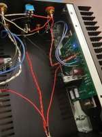
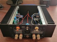
Now that I've successfully built a working ACA, maybe it's not perfect, but it was very satisfying, especially for my first time building an amp. I do want to hear this in dual mono at some point so I'll have a chance to build another one in the future... This month I bought another amp (Yamaha B-2), so I will practice some self restraint and not order another amp until at least October. hahaha
Next build may be a linear power supply or a pre-amp. I'm hooked!
Good luck MrJohn, seems you are almost there!
I'm done and it sounds great! I also have the F8 and it's inevitable that I'll compare them, but since the F8 is like 10x the cost, I can't help but to love this little ACA for what it is.
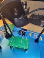
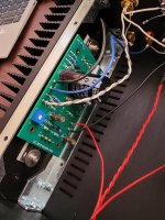
I've attached some pictures of my mimi-me ACA and some random build pics, even my fume extractor that I put together for this project. It goes straight out my window. Sorry neighbors!
Attachments
-
 MySystem_20210914.jpg39.2 KB · Views: 243
 -
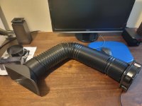 homemadeFumeExtractorExpanded.jpg67.8 KB · Views: 113
 -
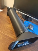 homemadeFumeExtractorCollapsed.jpg63.8 KB · Views: 125
 -
 ACA_BuildPics01.jpg70.6 KB · Views: 121
 -
 ACA_BuildPics05.jpg80.8 KB · Views: 190
 -
 ACA_BuildPics04.jpg76.1 KB · Views: 238
 -
 ACA_BuildPics06.jpg75.5 KB · Views: 237
 -
 ACA_BuildPics02.jpg67.2 KB · Views: 244
Congratulation with the build!
It seems only that it was the solder joints like the connectors where a large amount of metal has to be heated up that caused problems. So you can decide to only raise the temp to about 450 C for for these and keep 370 C for "normal" PCB solder joints. A solder tip that has a large amount of "heat-capacity" is good for heating up RCA connectors etc.
It is fine to blow on the joint after it has been soldered....to cool it down.
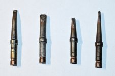
Here is a selection of the solder tips I use most.
No. 4 from the left is good for normal small PCB joints but not good for joints with a lot of metal. No. 2 from left is good for that. It is more massive and can better keep the temp up (has better heat reserve).
All the tips are 425 C Weller TCP no. 8 (800 F) (magnastat ("curie princip")) tips. Probably a bit "old fashioned" today but it still works.
Attachments
I use a 1.2 mm tip for almost all of my soldering. With Kester 63/37, I use a temp of 370 °C for small components and 400 °C for larger items such as RCA connectors.
Here is a selection of the solder tips I use most.
No. 4 from the left is good for normal small PCB joints but not good for joints with a lot of metal. No. 2 from left is good for that. It is more massive and can better keep the temp up (has better heat reserve).
All the tips are 425 C Weller TCP no. 8 (800 F) (magnastat ("curie princip")) tips. Probably a bit "old fashioned" today but it still works.
I forgot to answer that question. It's hard to tell from your picture, but I am using the smallest non-pointy end tip. It looks like a slanted flat head screwdriver. It I had to guess, it is probably 2mm on the blade portion of it. These are genuine hakko tips.
- Home
- Amplifiers
- Pass Labs
- Amp Camp Amp - ACA